
RGB LED Love Heart
The project utilizes a PIC12F683 microcontroller to control an RGB LED array arranged in the shape of a heart, providing a visually appealing display suitable for various occasions. The use of a plexiglass sheet enhances the aesthetic quality of the heart shape by diffusing the light emitted from the LEDs, thereby creating an attractive optical effect. The microcontroller is programmed to generate precise pulse-width modulation (PWM) signals, allowing for smooth transitions between colors and brightness levels.
The circuit design incorporates BC337 transistors to handle the higher current requirements of the LEDs, ensuring that the microcontroller operates within its safe limits. By utilizing 1K resistors, the design effectively limits the current flowing from the microcontroller to the transistors, protecting the PIC from potential damage due to excessive current draw. The choice of a 7805 voltage regulator provides a stable 5V supply, which is essential for consistent LED performance.
In terms of assembly, the project follows a systematic approach, starting with the placement of smaller components to avoid obstruction during soldering and culminating with the installation of the larger components. This methodical assembly process is critical for ensuring the integrity of the PCB and the overall functionality of the circuit.
The firmware developed for this project is integral to its operation, allowing for the dynamic control of the RGB LEDs. The interrupt-driven nature of the software PWM driver ensures that the LEDs can operate at high frequencies, providing a responsive and visually appealing light show. The inclusion of 32 brightness levels per color allows for fine-tuning of the display, enabling the creation of a wide range of colors and effects.
Finally, attention to detail in calculating the white balance across the RGB channels is crucial for achieving an even and aesthetically pleasing illumination. This ensures that when the LEDs are combined to produce white light, each color contributes equally to the overall brightness, enhancing the quality of the display. Overall, this project combines creativity with technical expertise, resulting in a functional and beautiful electronic display.This project creates a RGB LED lit love heart which is controlled by a PIC12F683 microcontroller. I designed the project as a gift for my wife on our 15th wedding anniversary (since she puts up with my addiction to electronics I thought she deserved something in return!). The love heart is made from a 200x150x6mm sheet of plexi-glass which is cut and sanded to create the optical effect and then mounted on the control board. Even if you are not into microcontrollers the display can be easily adapted to show any shape (or shapes) you like; furthermore any high-intensity LEDs can be used allowing you to create a static light display using little more than some LEDs, resistors and a power source. Note: The high brightness LEDs, PWM colour mixing and the varying intensities confuse my video camera a lot and it seems that the camera is overly sensitive to blue.
Despite this I hope the video gives you some idea of how the display functions; the display outputs 35 unique colours fading between each. To build this project you will need some basic tools in order to work with the plexiglass. In addition you will need a PCB (printed circuit board) which you can either make yourself, or use my supplied Eagle CAD files to order a PCB from one of the many board producers available on the Internet.
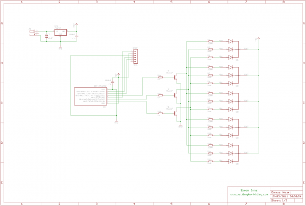
The controller board circuit diagram and PCB artwork are shown below. The Eagle CAD files for these items are included with the project files so you can adapt and alter the design to your needs (as is the firmware for the PIC12F683 written in HiTech PIC C). The board works by generating 3 software PWM signals from the PIC which control the overall brightness of the red, green and blue LEDs.
Since the LEDs require 30mA per led colour the circuit must be capable of sinking 90mA per colour or 5x90mA = 450mA which is way over the rated maximum of the PIC. Therefore BC337 small signal transistors (which can handle 800mA each) are used to sink the current coming from the LEDs.
The PIC controls the BC337 via 1K resistors which limit the current output from the PIC. The sinking current to each LED colour is limited to 30mA by 3 transistors (one for each colour). Since the RGB LEDs I used have different ratings for the red channel (lower forward current) the red channel requires a different resistance value from the green and blue channels. 5 volts of power (at 1A max) is supplied by the 7805 voltage regulator. If you use a power supply of 9 Volts, you shouldn`t need a heatsink on the 7805 as it will run only at around 50-60C.
The PCB should be assembled starting with the smallest components (the resistors) and working up to the largest (the 2. 1mm DC Jack). As a final step you should insert the PIC12F683 into its DIP-8 socket. If you want to program the PIC in-circuit (through the optional ICSP header) you will need to connect pins 2 and 3 from the header to Vcc and Vdd using some fine gauge wire in order for the ICSP programmer to function (I did not include this on the PCB as it would require 2 jumper wires which would degrade the clean look of the single-sided PCB design).
These wires can easily be added to the copper-side of the PCB. The RGB LEDs I used are capable of being driven at 30mA and produce a lot of light. You will need to check the datasheet for your LEDs and, if necessary, adjust the resistor values to make sure you do not supply too much current to your lights. If in doubt use 150R resistors (which is usually a safe maximum for most LEDs). The firmware is written in HiTech PICC and is included with the project files. The firmware consists of an interrupt driven software PWM driver which controls the RGB LEDs at 100Hz and supports 32 brightness levels per colour.
RGB LEDs do not have a uniform output brightness across the 3 available colours; this means that you have to be careful to calculate the white balance (ensuring the each colour produces the same brightness when mixing 🔗 External reference
Related Circuits
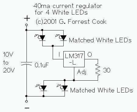
The LM317L and resistor act as a current regulator set to 40ma. Current flows from the battery through one pair of LEDs, through the regulator, through the other pair of LEDs, and back to the battery. The capacitor filters...
A request has been made to design a unique outdoor Christmas decoration in the form of an LED-illuminated star. The objective is to create a very bright display using 30 ultra-bright 8mm LEDs. The plan includes sanding the domes...
This is a tutorial for beginners who have recently started learning about electronics. The author has prior experience in programming with C and Python. The schematic presented in this tutorial is designed for novice electronics enthusiasts who are transitioning from...
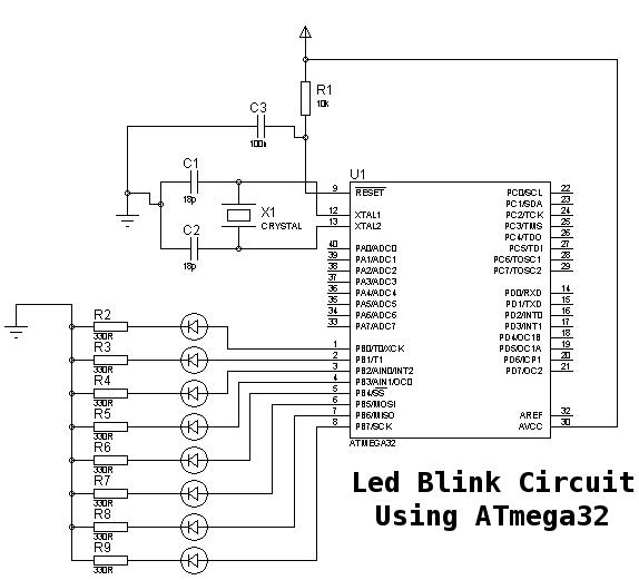
This is a basic tutorial for beginners using the ATmega32 microcontroller to get started. This program can be referred to as a "Hello World" for the ATmega. The ATmega32 microcontroller is a member of the AVR family, widely utilized in...

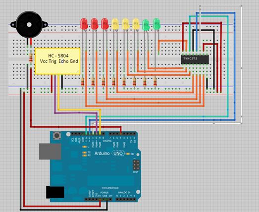
To create the circuit, connect a switch as an input and an LED as an output to the Arduino. The components required include a switch, an LED, a 10kΩ resistor, a 470Ω resistor, a blue or yellow jumper wire,...
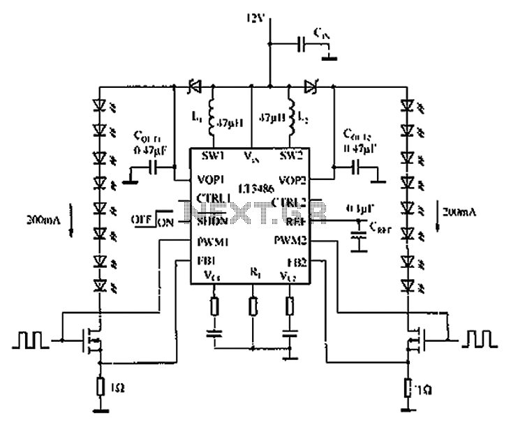
The automotive LED driver circuit diagram utilizes the LT3486. The LED is employed in the car's central high-mounted stop lamp (CHMSL), providing advantages such as faster achievement of the set brightness, higher efficiency, longer lifespan, and simplified design and...