Rgb-video-amplifier

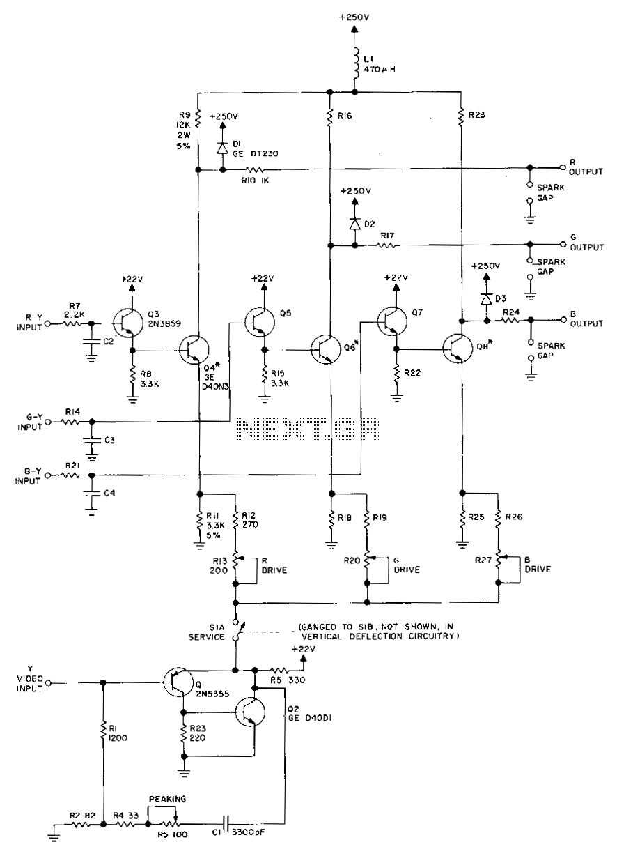
Transistors Q1 and Q2, along with their associated components, provide a low-impedance output necessary for driving the output stages. They enhance gain at high frequencies and improve video peaking for better transient response. Emitter followers Q3, Q5, and Q7 offer low-impedance drive to the output stages Q4, Q6, and Q8. The output stages apply color difference signals to their bases and luminance signals to their emitters, facilitating matrixing. This matrixing generates composite output information for the picture tube, which includes both luminance and chroma data. Transistors Q4, Q6, and Q8 require small heat sinks, with Staver type F7-2 or equivalent recommended. If a TO-18 lead arrangement is preferred, use 2N5825 for Q3, Q5, and Q7, and GE GET3638A for Q1.
Transistors Q1 and Q2 are configured to deliver a low-impedance output, which is vital for effectively driving subsequent output stages in the circuit. Their design ensures that high-frequency signals are amplified, providing enhanced gain that is essential for maintaining signal integrity, especially in video applications. This is complemented by the peaking of video signals, which optimizes transient response, thus improving the overall performance of the system.
Emitter followers Q3, Q5, and Q7 serve a critical role by providing a low-impedance drive to the output stages, which include transistors Q4, Q6, and Q8. This configuration allows for efficient signal transfer and minimizes distortion, ensuring that the output stages can operate effectively under varying load conditions. The application of color difference signals to the bases of Q4, Q6, and Q8, alongside luminance signals applied to their emitters, facilitates the matrixing process. This matrixing is essential for generating a composite output that combines the luminance and chroma information required for display on the picture tube.
The output stages, through their strategic arrangement and connection, ensure that the composite signal produced is robust and suitable for driving the picture tube, which is critical for achieving high-quality visual output. To manage thermal conditions, transistors Q4, Q6, and Q8 are designed to operate with small heat sinks, and Staver type F7-2 or equivalent heat sinks are recommended to ensure reliable operation without overheating.
For applications requiring a specific lead arrangement, the circuit can accommodate alternative components. Specifically, for a TO-18 lead configuration, the 2N5825 transistor can be utilized for Q3, Q5, and Q7, while the GE GET3638A is suggested for Q1. This flexibility in component selection allows for customization based on specific design requirements or constraints, ensuring that the circuit can be adapted to meet various operational needs while maintaining performance standards.Transistors Ql and Q2 and their associated components provide: a low-impedance output with the necessary power to drive the output stages, give increased gain tohigh frequencies, and peaking the video for enhanced transient response. Emitter followers Q3, Q5, and Q7 provides low-impedance drive to output stages, Q4, Q6, andQS. The output stages, with the color difference signals applied to their bases and the luminance signals to their emitters, perform matrixing.
The matrixing results in composite output information, to the picture tube, which contains both luminance and chroma information. Q4, Q6, and Q8 require small heat sinks. Staver type F7-2 or equivalent are recommended (Note: If T0-18 lead arrangement is desired, use 2N5825 for Q3, Q5 and Q7, and GE GET3638A for Q1.)