
RIAA Compensated Stereo Preamp
The described circuit functions as a critical interface between a turntable and a stereo amplifier that lacks dedicated phono inputs. The RIAA preamplifier is essential for ensuring that the audio signal from vinyl records is appropriately processed, maintaining the integrity of the original sound recording. The RIAA equalization curve compensates for the inherent limitations of vinyl records, which are produced with varying levels of bass and treble frequencies to optimize the physical space on the record surface.
The circuit is designed around two dual operational amplifiers, which are versatile components that amplify electrical signals. The use of dual Opamp packages allows for efficient space utilization on the circuit board while providing the necessary amplification for both the left and right audio channels. The gain characteristics of the amplifier are tailored to match the RIAA curve: it amplifies low-frequency signals by 20 dB to counteract the natural roll-off of bass during the cutting process of vinyl records, maintains a flat response at mid frequencies, and attenuates high frequencies by 20 dB to prevent distortion and ensure a balanced output.
For those interested in custom circuit board creation, the instructions provided in the "Custom Etched Circuit Boards" section offer a step-by-step guide for designing and fabricating a tailored PCB for this preamp circuit. The availability of full-size artwork facilitates the process, allowing for precise layout and component placement, which is crucial for maintaining signal integrity and minimizing noise. This preamp circuit is not only functional but also serves as an educational tool for understanding the principles of audio signal processing and the importance of RIAA equalization in vinyl playback systems.If your stereo amplifier does not have an input for a record player, you should use this circuit between your turntable and your amplifier. The output of your turntable follows a gain-bandwidth curve called the RIAA compensation curve. The standard AUX input on your stereo does not. Records will sound very strange without an RIAA preamp. The RIAAcompensation curve was adopted in the mid 1950s, as a way of dramatically improving the fidelity of playback. This curve takes into account the limitations of the mechanican recording system on the record surface. At low frequencies, this amplifier provides 20dB of gain. At medium frequencies it provides no gain, and at high frequencies it provides 20dB of attenuation. Note that only two Opamp packages are used. Each type is actually a dual Opamp. The left and right amps share one amp of each type from each dual package. This circuit is also used as the example for the "Custom Etched Circuit Boards" section. In that section you will find instructions for making a custom circuit board for this preamp. If you want to make your own circuit board for this project, you can download full size artwork there as well.
🔗 External reference
Related Circuits
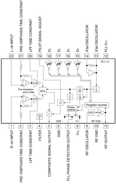
The BH1417 FM Transmitter architecture from RHOM is a compact solution that integrates multiple features into a single package. It includes pre-emphasis and a limiter to ensure that music is transmitted at the desired audio level, as well as...
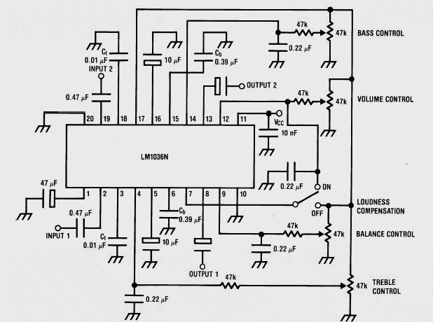
This weblog discusses electronic circuit schematics, PCB design, DIY kits, and electronic project diagrams. It features a stereo tone control circuit built using the LM1036 integrated circuit (IC). This control circuit adjusts bass, treble, volume, and the balance between...
The intermodal servo preamplifier circuit operates at 115V and 60Hz, designed to provide a differential output for a servo motor amplifier. It features an inverting connection using an operational amplifier (op-amp), along with an additional op-amp configured to create...
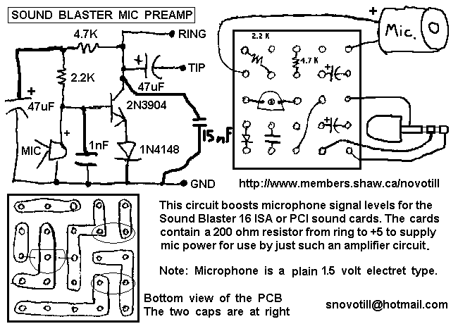
The Sound Blaster 16 PCI and Sound Blaster 16 ISA do not have a very sensitive microphone input. This little one transistor amplifier is powered directly from the microphone jack on the sound card and has LOTS of gain....
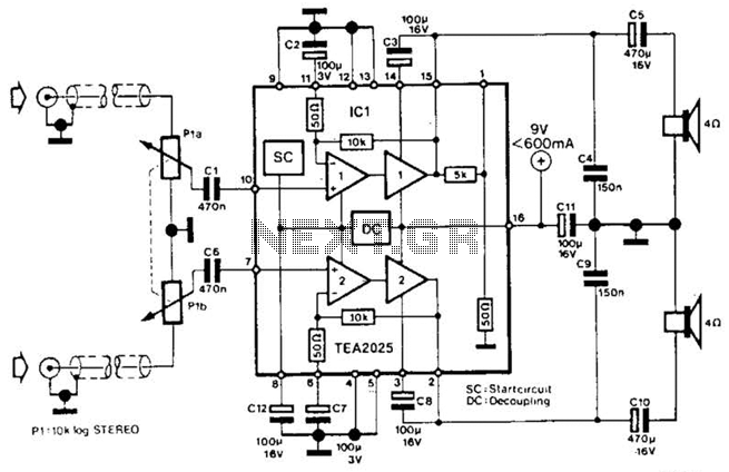
Using a Thomson TEA2025, this stereo amplifier delivers 1 W per channel into a 4-ohm load with a 9-V supply. The input sensitivity is 25 mV peak-to-peak for full output. It is important to ensure that pins 4, 5,...
To complement the 60 Watt MOSFET audio amplifier, a high-quality preamplifier design was necessary. A discrete component topology, utilizing +24V and -24V supply rails, was selected, minimizing the transistor count while ensuring low noise, very low distortion, and a...