
robot guts
The circuit described employs a straightforward yet effective design utilizing a pair of photo resistors (LDRs) and a dual voltage comparator IC. The orientation of the headlights and photo cells facing the ground suggests that the system is intended for ground detection or navigation based on light levels.
The use of three LEDs per side is strategic; it ensures that adequate brightness is achieved while managing the limitations of the 9V power supply. When connected in series, the forward voltage drop of each LED must be considered; therefore, the inclusion of transistors allows for the control of the LEDs without exceeding the supply voltage. The transistors act as switches, enabling or disabling the LEDs based on the comparator's output.
The NTE943M comparator plays a crucial role in the circuit's functionality. It compares the voltage levels from the two sets of photo resistors. When one set of LDRs detects more light, it generates a lower resistance, resulting in a higher voltage output. The comparator processes these signals and determines which set of LEDs should be activated. This feedback mechanism allows the robot to respond dynamically to changes in light conditions, effectively guiding its behavior based on environmental inputs.
In summary, this circuit exemplifies a robust design for light-sensitive applications, utilizing basic electronic components to achieve a functional and responsive system. The integration of the comparator and transistors ensures efficient operation while maintaining simplicity in the overall architecture.The headlights and photo cells will face the ground, so I find it easiest to imagine that the whole circuit is upside down Why 3 LEDs per side As far as I can tell, because you can`t power three in series from a single 9V battery without a little help, and this way Cook could include transistors in the circuit. The robot`s thinking is simple. The lone IC is an NTE943M low power, low offset, dual voltage comparator. It identifies which set of photo resistors is running at a higher voltage (a function of increased resistance, meaning which set is receiving less light), and lights the set of LEDs corresponding with the other set ” the set receiving more light. 🔗 External reference
Related Circuits
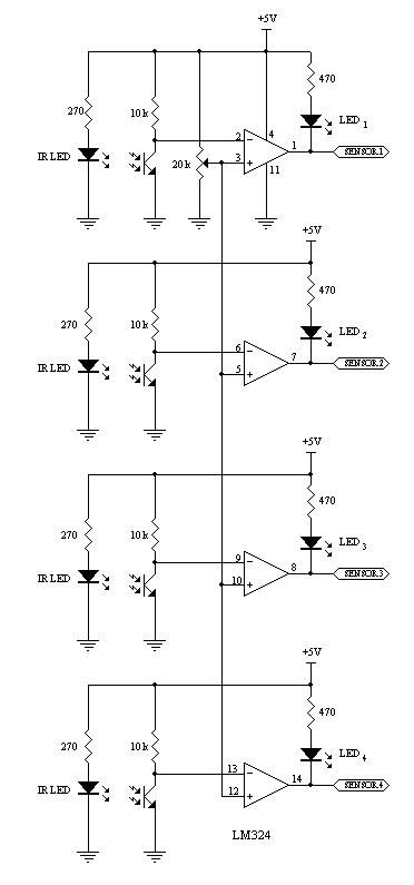
This robot utilizes two motors to control the rear wheels, while the single front wheel is free to move. It is equipped with four infrared sensors located on the underside to detect black tracking tape. When the sensors identify...
These are operational amplifier (op-amp) based filters that are particularly effective within the audio frequency range. The calculators for these filters utilize formulas and tables from the book "Electronic Filter Design Handbook" by Arthur B. Williams. Bandpass filters allow...
This line-following robot sensor, also known as a surface scanner for robots, is a compact, stamp-sized infrared proximity detector designed for short-range detection (5-10 mm). It is built around a standard reflective opto-sensor, the CNY70 (IC1). In various applications,...

The schematic for controlling the motors is divided into three main sections, each serving a distinct function. The primary components featured in the schematic include the PIC 18F252 microcontroller, the SN754410 motor driver, and 2N2222 transistors. At the top...
The remote control robot circuit is illustrated in the accompanying figure. Figure 2-36(a) presents the circuit diagram, while figure 2-36(b) depicts the operating timing diagram. The robot's rotation process involves an ultrasonic launching circuit, which consists of a 40...
This project is based on the Miller solar engine and does not involve any digital electronics. A robot is defined as a "mechanical intelligent agent that can perform tasks independently." Importantly, this definition does not specify any particular form....