
ROM and RAM Emulator for 8051
The circuit involves the integration of a slave microcontroller, specifically the SAB-C515, which serves as an interface for managing peripheral devices and executing programmed tasks. The presence of a green LED indicates that the slave MCU is powered and operational, providing a visual confirmation of its status. The MAX690 is employed to ensure that the memory contents of the slave MCU remain intact during power outages or shutdowns, thus preventing data loss.
When programming the SAB-C515, developers can transition seamlessly to the AT89-family microcontrollers by adjusting the port addresses, enhancing compatibility and streamlining development processes. This flexibility is particularly beneficial in applications requiring rapid prototyping or modifications.
The architecture of the SAB-C515 includes a second interrupt enable register, which is crucial for managing interrupt priorities effectively. This feature allows for more sophisticated interrupt handling compared to the standard 8051 architecture. Additionally, the SAB-C515's Timer 2 (T2) has been expanded to function as a compare and capture unit, facilitating advanced timing operations and event-driven programming. It is essential to adhere to the guidelines regarding the manipulation of unused bits, as improper handling could lead to unpredictable behavior in the system.
Overall, the design emphasizes reliability and flexibility, making it suitable for various embedded applications that require robust microcontroller performance and efficient resource management.If the green LED is on, the slave MCU is enabled. The MAX690 keeps the memory contents during power off. No resouces of the slave MCU are used. Wenn a SAB-C515 is used, it is possible to develop programs for the AT89-family easily by changing simply the port addresses. Remember that the address of the interrupt priority register at the 8051 is at the SAB-C515 the second interrupt enable register! Be careful also when you use the T2 of SAB-C515, compared to 8052 it is extended to a compare and capture unit. Do not ever write any 1`s to bits that are not used by the basic 8051 architecture. 🔗 External reference
Related Circuits
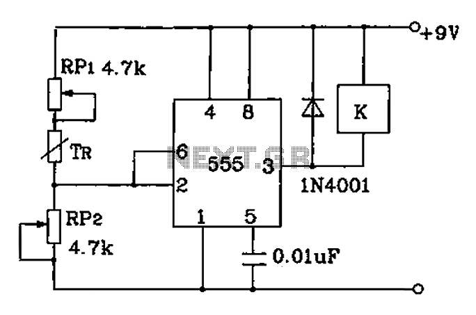
Adjust RP1 and RP2 to set the preset temperature control point. The 555 circuit is configured as a Schmitt inverter circuit that automatically controls a relay device. This forms part of the T-121 temperature control circuit, which includes a...
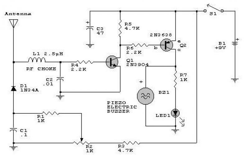
This circuit responds to RF signals below the standard broadcast band up to over 500 MHz and provides both visual and audible indications when an RF signal is detected. By adjusting the bias of diode D2 with the R2...
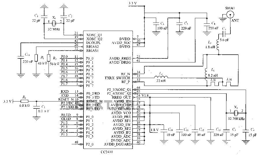
Figure C1 and C2 depict a 22 pF capacitor connected to a 32 MHz crystal oscillator circuit, which utilizes a quartz crystal for standard operation. Capacitors C3 and C4, each rated at 15 pF, are connected to a 32.768...
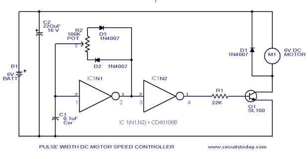
A simple PWM motor speed control circuit with a diagram and schematic for low power DC motors. This easy-to-make PWM DC motor controller is created using the IC CD40106B. The PWM (Pulse Width Modulation) motor speed control circuit utilizes the...
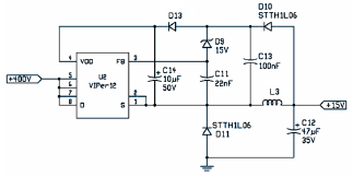
The following file is an application note describing the two stages of an electronic ballast for a 250 W HID metal halide lamp. The components include. The application note outlines a two-stage electronic ballast designed specifically for a 250 W...
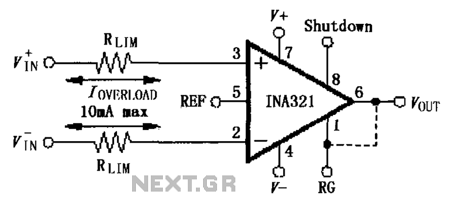
The input current protection circuit for the INA321/322 is illustrated. The INA321/322 features input terminal electrostatic discharge (ESD) protection diodes that become conductive when the input voltage exceeds the supply voltage by 500mV. The protection diodes will conduct, and...