
Room Noise Detector Circuit
The circuit comprises a miniature electret microphone that serves as the sound input device. The microphone converts sound waves into an electrical signal, which is then fed into the first op-amp configured as a non-inverting amplifier. This stage amplifies the weak audio signal to a suitable level for further processing. The gain of the op-amp can be adjusted depending on the desired sensitivity of the microphone.
Following the first op-amp, the signal is routed to a second op-amp, which further amplifies the signal and may also include a comparator function to determine if the amplified signal exceeds any of the predetermined thresholds. The output of the second op-amp is connected to a threshold detection circuit that utilizes resistors to set the reference voltages corresponding to the 50 dB, 70 dB, and 85 dB levels.
The circuit's operation is controlled by a switch (SW1), which allows the user to select the desired threshold level. In the first position, the circuit is powered off to conserve energy. In the second, third, and fourth positions, the circuit is powered on, and the sensitivity threshold is adjusted accordingly. When the noise level exceeds the selected threshold, the output of the second op-amp triggers a transistor or a similar switching device to activate the LED.
The LED serves as a visual indicator, flashing to signal that the ambient noise level has crossed the set threshold. The flashing behavior can be implemented using a simple timing circuit, which may consist of additional passive components such as resistors and capacitors to create a blinking effect. The current draw of the circuit is relatively low, at 1 mA when the LED is off, and increases to 12-15 mA when the LED is continuously lit, ensuring that the circuit remains efficient while providing clear visual feedback.This circuit is intended to signal, through a flashing LED, the exceeding of a fixed threshold in room noise, chosen from three fixed levels, namely 50, 70 & 85 dB. Two Op-amps provide the necessary circuit gain for sounds picked-up by a miniature electret microphone to drive a LED.
With SW1 in the first position the circuit is off. Second, third and fourth positions power the circuit and set the input sensitivity threshold to 85, 70 & 50 dB respectively. Current drawing is 1mA with LED off and 12-15mA when the LED is steady on.. 🔗 External reference
Related Circuits
This project was completed successfully, achieving the desired frequency and strength. For assistance, please reach out for support in resolving any issues. The project involves the design and implementation of an electronic circuit that operates at a specified frequency and...
Constantly changing light and sound analog controller circuit 02 The circuit described is an analog controller designed to modulate light and sound in a dynamic manner. It typically utilizes components such as operational amplifiers, resistors, capacitors, and transistors to achieve...
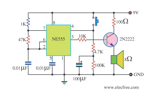
This is a danger beep circuit. It uses a 555 integrated circuit configured as a stable multivibrator that provides a duty cycle of 5% to drive a loudspeaker. The danger beep circuit utilizes the 555 timer IC, a versatile and...
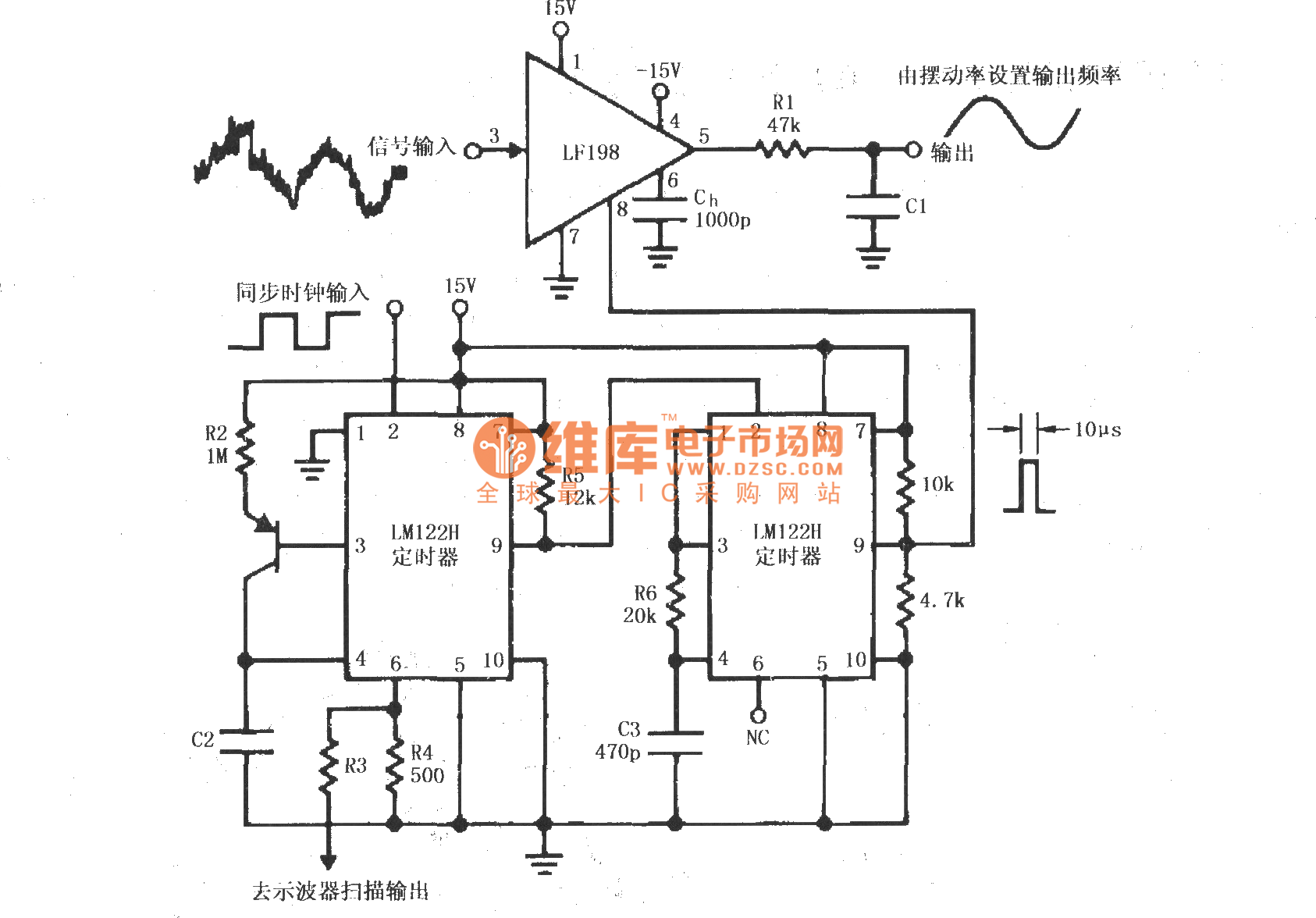
A synchronous clock signal is fed into a cascade of timer circuits composed of two LM122H devices. The synchronization clock is then converted into a pulse of the desired width, which is added to the LF198 logic end (pin...
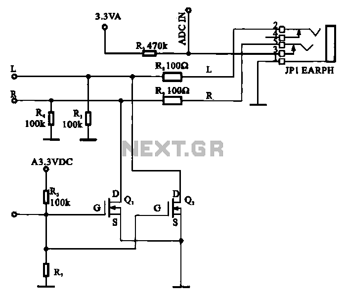
A field-effect transistor (FET) is utilized in a headphone circuit designed to function as a silencer tube. The circuit integrates L from the digital signal processing unit and R from the audio signal into the headphone jack's mute control...
This circuit was submitted by Graham Maynard from Newtownabbey, Northern Ireland. It has an exceptionally fast high-frequency response, as demonstrated by applying a 100kHz square wave to the input. All graphs were produced using Tina Pro. The circuit in question...
Warning: include(partials/cookie-banner.php): Failed to open stream: Permission denied in /var/www/html/nextgr/view-circuit.php on line 713
Warning: include(): Failed opening 'partials/cookie-banner.php' for inclusion (include_path='.:/usr/share/php') in /var/www/html/nextgr/view-circuit.php on line 713