
Safety Guard
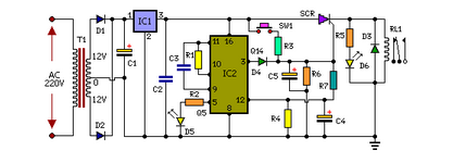
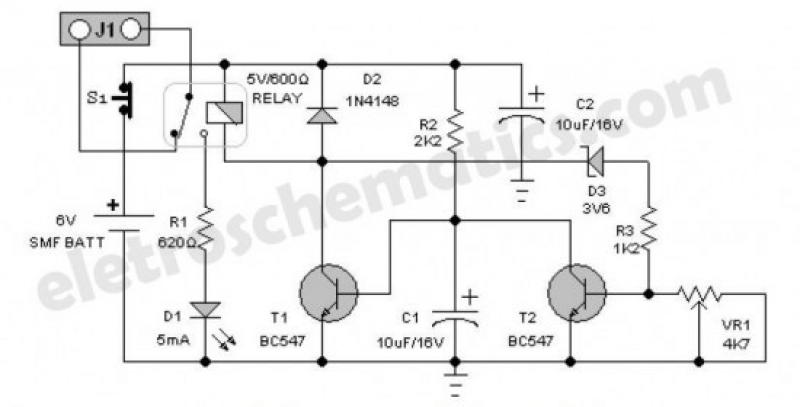
The time delay circuit is designed to safeguard sensitive electronic devices from immediate power surges that can occur when the power supply is restored. It operates by incorporating a delay mechanism that ensures a brief waiting period before the appliances are powered on. This delay allows any transient voltage spikes to dissipate, thus preventing potential damage to the connected devices.
The circuit typically consists of a relay, a resistor-capacitor (RC) timing network, and a diode for flyback protection. Upon receiving power, the RC network begins charging, and the time delay is determined by the values of the resistor and capacitor. Once the voltage across the capacitor reaches a certain threshold, it activates the relay, closing the circuit and supplying power to the connected appliances.
Additionally, a diode is placed in parallel with the relay coil to protect the circuit from back EMF generated when the relay is de-energized. This protection is crucial for maintaining the integrity of the control circuitry.
Overall, this time delay circuit is an effective solution for enhancing the reliability and longevity of home appliances by mitigating the risks associated with voltage spikes during power restoration.Protect your home appliances from voltage spikes with this simple time delay circuit. Whenever power to the appliances is switched on or resumes after mai.. 🔗 External reference
Related Circuits

SI and S2 must be pressed within 200 ms of each other to activate K1. The hold time is adjustable via K7. Additionally, the overlap time of SI and S2 can be modified by changing C1 and C2 or...
The optical safety switch circuit includes a power supply circuit, a light control circuit, and a control implementation circuit (switch circuit). The power circuit is made up of a power transformer (T), a bridge rectifier (UR), and a filter...
This simple door chime protects the door and emits a loud alarm tone in the event of a theft attempt. The circuit is straightforward and battery-operated. A Normally Closed (NC) reed switch and magnet are utilized to trigger the...
Protect your locker or briefcase from theft using this pocket-sized gadget. It emits a loud police siren to attract attention. The circuit utilizes a single integrated circuit (IC). This circuit is designed to provide a compact and effective security solution...
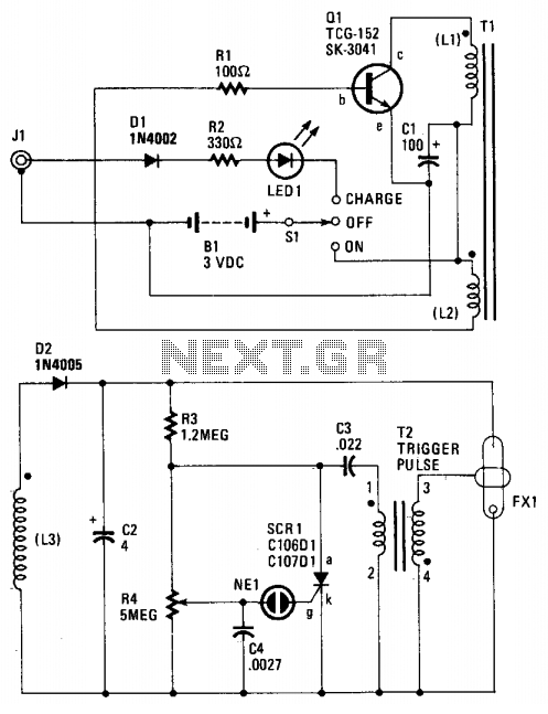
When the switch SI is activated, power is supplied to an oscillator that consists of Q1, R1, C1, L1, and L2. Coil L1 serves as the primary winding of transformer T1, while L2 functions as the feedback winding. As...
An emergency light is a light source designed to be available during emergencies. It operates automatically and is powered by a rechargeable battery. An emergency light system typically consists of several key components: a light source, a rechargeable battery, a...
Warning: include(partials/cookie-banner.php): Failed to open stream: Permission denied in /var/www/html/nextgr/view-circuit.php on line 713
Warning: include(): Failed opening 'partials/cookie-banner.php' for inclusion (include_path='.:/usr/share/php') in /var/www/html/nextgr/view-circuit.php on line 713