
Schematic for voltage regulation via lm317
The described circuit involves the use of an LM317 voltage regulator as the primary component for the lab power supply. The LM317 is capable of providing a stable output voltage that can be adjusted based on the application requirements. The integration of a switchable current limiter is essential for protecting sensitive measuring equipment, such as a digital multimeter, during current measurement tasks.
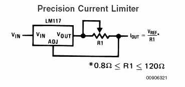
To design the current limiter, it is necessary to calculate the resistor values based on the desired output current. The formula Iout = Vref/R1, where Vref is typically 1.25V for the LM317, allows for determining the resistance needed to limit the current. For instance, to limit the output current to 0.25A, a resistor value of 5 ohms is calculated using R1 = 1.25V/0.25A.
Incorporating a rotary switch for adjustable current limiting requires careful consideration of the switch's specifications and the resistor ratings. The switch must be rated for the maximum voltage and current that will be passing through it, which in this case is 32V DC and 1A. Standard 0.25W resistors may not be sufficient for higher current applications; thus, resistors with appropriate power ratings should be selected to ensure reliability and safety.
The transformer chosen for this application is a 15VA transformer with dual outputs of 15V at 0.5A. This transformer can be configured in series or parallel to provide different voltage and current combinations. When connecting in series, the output voltage doubles to 30V while the current capacity remains at 0.5A. Conversely, when configured in parallel, the voltage remains at 15V, but the current capacity increases to 1A. The addition of a switch to facilitate this change is advantageous; however, it is crucial to ensure that the switch can handle the increased voltage and current without overheating or failing.
Overall, the design of the lab power supply with a switchable current limiter and adjustable output voltage is feasible with careful component selection and proper circuit layout. This ensures that the system operates safely and effectively, meeting the intended application requirements.A simple lab-psu using the lm317, based on the first schematic. to prevent damages to my dmm when measuring mA, i`d like to include a switchable current limiter. but i`m not sure if i understand those schematics and how i could integrate it. so here are my questions: 1. 2 s. schematic 2: when Iout = R1/Vref and Vref = 1, 25v (that should be the correct value, when i understand it right), then i can calculate resistor values via R1=1, 25/Iout (for example R1 = 1, 25/0, 25 = 5 ohm to limt the current to 0, 25A) 1. 3 i`d like to use a rotary switch to integrate an adjustable current limiter: how can i calculate the minimal necessary specs of switch and resistors, when max.
32v dc and 1a current flow through the wires are simple 0, 25w-resistors/switchers enough most likely a 15VA transformer with 2x15v, 2x0, 5A will feed the psu. are there any disadvantages in adding a switch to change between series- and parallel-connection of the secondaries (to get 15v/1A vs.
30v/0, 5A) 🔗 External reference
Related Circuits
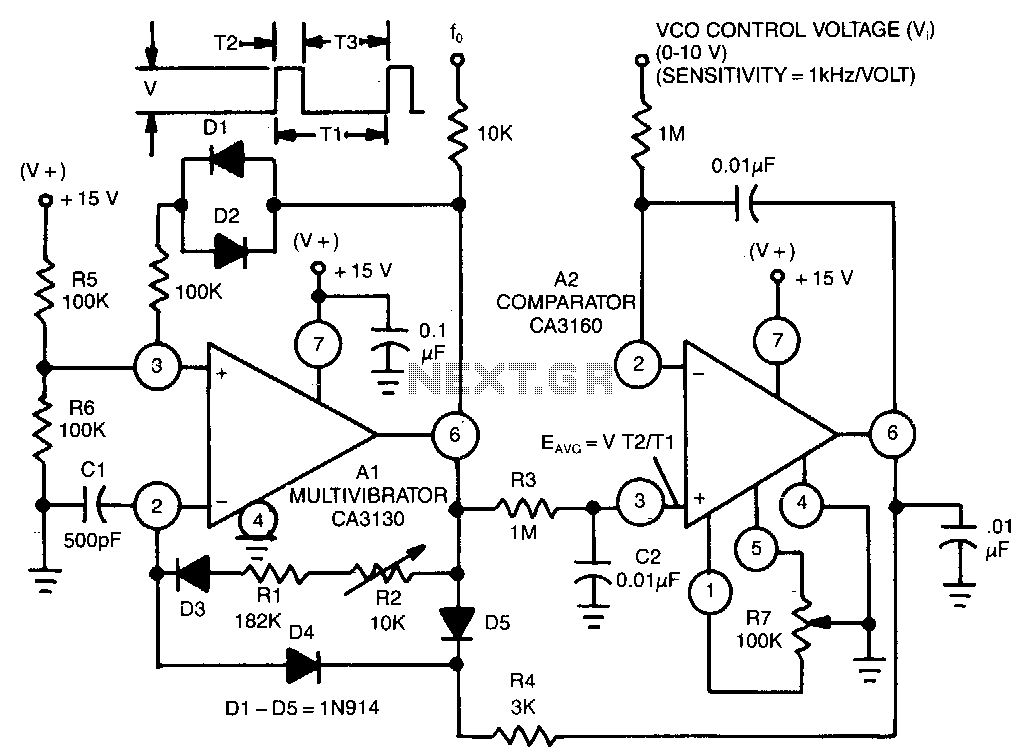
This circuit utilizes a CA3130 BiMOS operational amplifier as a multivibrator and a CA3160 BiMOS operational amplifier as a comparator. The oscillator exhibits a sensitivity of 1 kHz/V, with a tracking error of approximately 0.02% and a temperature coefficient...
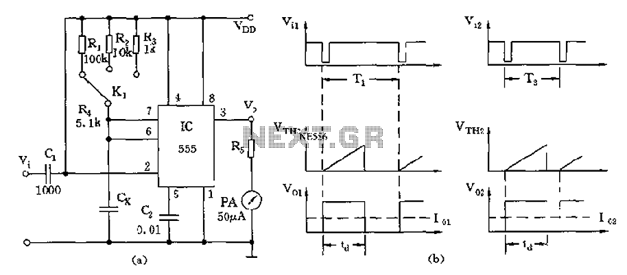
The circuit utilizes a 555 timer along with timing resistors R1 to R3 and a measured capacitance Cx to create a capacitance meter. The principle of capacitance measurement in a one-shot circuit is based on the relationship between the...
A voltage-to-frequency converter can be constructed using the LM231/331 chip, making it a cost-effective solution for applications such as analog-to-digital conversion and frequency-to-voltage conversion over extended periods. The LM231/331 series of voltage comparators can be effectively utilized to design a...
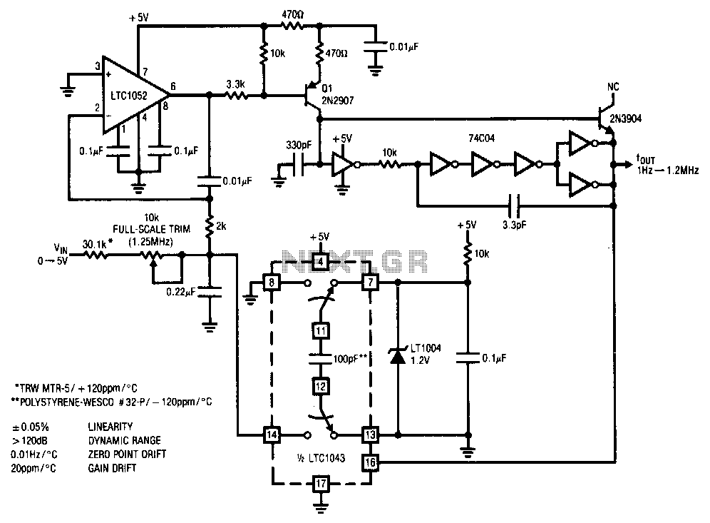
This stabilized voltage-to-frequency converter operates within a range of 1 Hz to 1.25 MHz, featuring a linearity of 0.05% and a typical temperature coefficient of 20 ppm/°C. The circuit is powered by a single 5-V supply. It employs a...
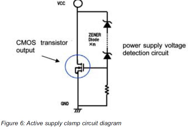
This article presents a high reliability 1200V High Voltage Integrated Circuit (1200V HVIC) for half bridge driver applications, aimed at reducing the IC's supply current by approximately 50%. The 1200V High Voltage Integrated Circuit (HVIC) is designed specifically for half-bridge...
The Dynaco Mark III is the highest power amplifier that was widely sold under the Dynaco name. There was a higher power amp (the Mark VI), but it wasn't widely available. The Dyna MKIII has a basic design flaw...