
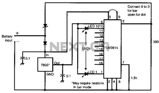
Schmitt Trigger VU Meter
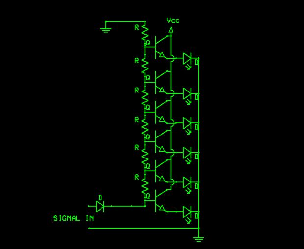
The voltage divider in the schematic serves to scale down the input voltage to a level suitable for the Schmitt trigger's threshold requirements. A voltage divider typically consists of two resistors, R1 and R2, connected in series across the input voltage source. The output voltage, which is fed into the Schmitt trigger, is taken from the junction of these two resistors. The values of R1 and R2 can be selected based on the desired output voltage using the formula:
V_out = V_in * (R2 / (R1 + R2))
where V_out is the voltage at the junction of the resistors, and V_in is the input voltage. This setup allows for precise control over the input signal levels, ensuring that the Schmitt trigger operates correctly.
The Schmitt trigger itself is a type of comparator that provides hysteresis, allowing for clean transitions between high and low states in digital circuits. This is particularly useful in noisy environments where the input signal may fluctuate around the threshold levels. The output of the Schmitt trigger will change state when the input voltage crosses a defined upper or lower threshold, providing a stable output signal.
In summary, the careful design of the voltage divider and Schmitt trigger configuration is crucial for ensuring reliable operation in electronic circuits, particularly in applications requiring noise immunity and precise signal processing.If you look carefully at the schematic you will notice the input is feed into the voltage divider. This is because the Schmitt Triggers all turn on a.. 🔗 External reference
Related Circuits
This Class E RF amplifier is capable of delivering up to 400 watts of RF output, depending on the input voltage and tuning parameters (current). The amplifier employs economical IXDD414 Driver ICs, with one driver for every two MOSFETs....
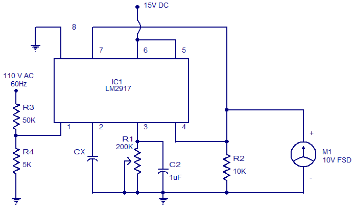
The circuit diagram of a simple capacitance meter using IC LM2917 is illustrated. The LM2917 is a high-gain monolithic frequency-to-voltage converter IC from National Semiconductors. While the primary application of the LM2917 is in tachometers, it can also be...
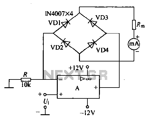
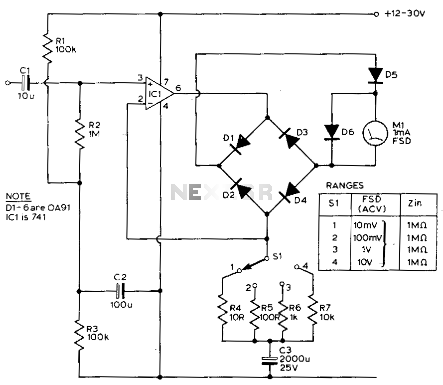
An operational amplifier, a diode bridge rectifier, and DC mA AC voltmeter tables are illustrated in the figure. The operational amplifier used is the LM324. The measured AC voltage is applied to the inverting terminal of the operational amplifier,...
Many amateur receivers are equipped with an S meter that does not operate logarithmically. The proposed circuit is intended to enhance such receivers. Although integrated circuits like the CA3089 or CA3189 are not commonly used today, they play a...
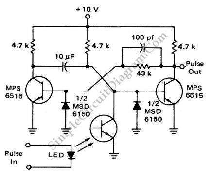
This is a flash-triggered (photo-driven) circuit that produces a pulse with a constant predetermined width. This circuit can be used to control any device. The flash-triggered circuit operates by utilizing a photodetector, which is typically a photodiode or phototransistor, to...
This circuit exhibits a flat frequency response from 8 Hz to 50 kHz, maintaining a -3 dB level at the 10 mV range. Furthermore, while the upper frequency limit remains consistent across less sensitive ranges, the lower frequency limit...