
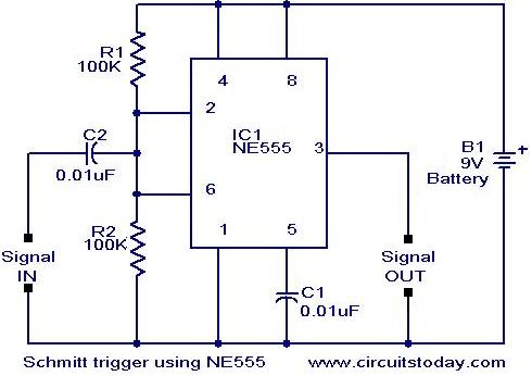
Scmitt Trigger circuit using NE 555
The 555 timer's versatility extends beyond simple timing applications, allowing for the implementation of various signal processing functions. In the Schmitt Trigger configuration, the two comparators provide hysteresis, which enhances the noise immunity of the circuit by ensuring that the output state changes only when the input signal crosses specific threshold levels. This is particularly useful in digital signal processing where clean transitions between high and low states are necessary.
The voltage divider formed by R1 and R2 determines the precise biasing point at 1/2 Vcc, which is critical for the proper operation of the Schmitt Trigger. The choice of resistor values affects the response time and the stability of the output. For instance, increasing the resistance values will slow down the response time, while decreasing them will result in a faster response but might introduce instability if the values are too low.
The capacitor C1 plays a crucial role in shaping the input signal. By selecting a smaller capacitance value, the circuit can effectively differentiate fast-changing signals, making it suitable for applications requiring rapid signal processing. The combination of C1 with R1 and R2 creates a high-pass filter effect, allowing only the high-frequency components of the input waveform to pass through. This characteristic is particularly beneficial for applications such as pulse-width modulation (PWM) and signal conditioning.
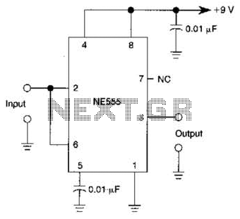
Overall, the 555 timer in a Schmitt Trigger configuration is a powerful tool for engineers, enabling the design of robust and efficient digital circuits capable of handling various input signal conditions.Apart from the timing functions, the two comparators of the 555 timer can be used independently for other applications. One example is a Schmitt Trigger shown here. The two comparator inputs (pin 2 & 6) are tied together and biased at 1/2 Vcc through a voltage divider R1 and R2.
Since the threshold comparator wil trip at 2/3 Vcc and the trigger comp arator will trip at 1/3Vcc, the bias provided by the resistors R1 & R2 are centered within the comparators trip limits. By modifying the input time constant on the circuit, reducing the value of input capacitor (C1) to 0.
001 uF so that the input pulse get differentiated, the arrangement can also be used either as a bistable device or to invert pulse wave forms. In the later case, the fast time combination of C1 with R1 & R2 causes only the edges of the input pulse or rectangular waveform to be passed.
These pulses set and reset the flip-flop and a high level inverted output is the result. 🔗 External reference
Related Circuits
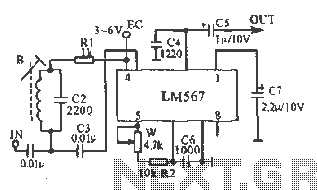
This figure illustrates the schematic of the LM567 SCA broadcast reception information machine. The LM567 serves as a narrow-band phase-locked loop designed primarily for SCA broadcast demodulation. The configuration includes a potentiometer (W) and capacitor (C6) that determine the...
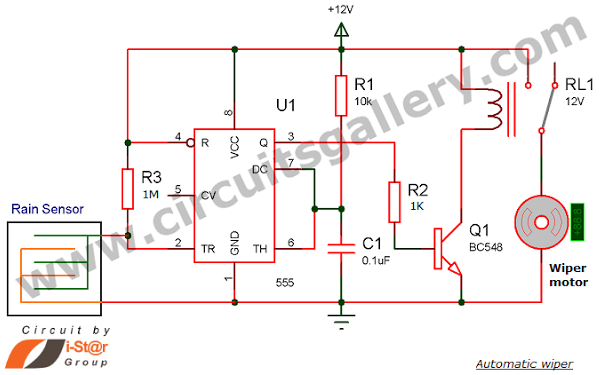
Have you seen Audi, Lexus, or Ford rain-sensing wipers and wondered how they operate in these vehicles? They are controlled by sensors located at the center of the windscreen, which detect raindrops and activate the wiper motor. The functioning...
MSP430 microcontroller and I2C-compatible slave peripheral device. Temperature measurement tasks can be accomplished in a variety of ways. The MSP430 microcontroller is a low-power, 16-bit device widely used in embedded systems, particularly for applications requiring efficient power management and precise...
In addition to its primary function as a headphone amplifier, the circuit is suitable for various applications requiring a wide bandwidth low power amplifier. It is constructed using an operational amplifier (op-amp), with its output current enhanced by a...
The requirement was to add a digital readout to a manually operated bend roller machine to accurately monitor the amount of material fed into the machine. The readout should be user-friendly, requiring no setup other than initial calibration, and...
A 555 IC is configured to function as a Schmitt trigger. Inputs above and below the threshold level will turn the circuit on and off, producing a square wave output. The 555 timer integrated circuit (IC) is a versatile device...
Warning: include(partials/cookie-banner.php): Failed to open stream: Permission denied in /var/www/html/nextgr/view-circuit.php on line 713
Warning: include(): Failed opening 'partials/cookie-banner.php' for inclusion (include_path='.:/usr/share/php') in /var/www/html/nextgr/view-circuit.php on line 713