
Scoobas Solution Sensing Tactic
The Scooba robot employs a sophisticated liquid sensing system to ensure efficient operation during cleaning cycles. This system is primarily based on two sensor sub-systems: the "Clean-Empty" and "Waste-Full" sensors, which work in tandem to monitor the presence and condition of the cleaning solution. The sensors utilize a voltage divider configuration, where the resistance of the liquid is a critical factor in determining whether the cleaning solution is adequate or if the waste tank is full.
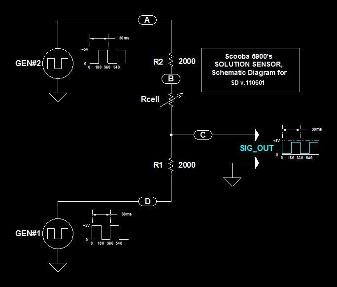
The schematic diagram illustrates a simplified version of the sensor circuits, focusing on the essential components without extraneous details. The low-frequency square-pulse waveform generators provide excitation to the sensor electrodes, creating a measurable signal based on the conductivity of the liquid. The phase-shifted outputs from these generators ensure that the signals can be effectively processed to determine liquid presence.
The resistors R1 and R2 serve as fixed components in the voltage divider, while Rcell represents the variable resistance corresponding to the liquid being measured. The interaction between these resistances allows the MCU to assess the liquid's conductivity and make real-time decisions regarding the cleaning process. The signal generated from the voltage divider feeds into the MCU, which interprets the data to ensure that the robot operates within the parameters necessary for optimal cleaning performance.
In summary, the liquid sensing system of the Scooba robot is a critical component that enables it to function effectively. The schematic representation provides a foundational understanding of how the system operates, emphasizing the importance of the voltage divider and the role of the square-pulse generators in creating a reliable signal for the MCU to process. This knowledge is essential for both current owners and those looking to modify older models, such as the 5900, to enhance their performance with alternative cleaning solutions.This document has several purposes, and a primary one is to record what I have learned about the means that a Scooba robot uses to detect: a) the presence of an acceptable cleaning solution being delivered to its pump, and b) the excess presence of used solution collected off the floor and stored in the Tank`s waste chamber. In the same manner tha t this document will serve to remind me about Scooba`s liquid sensing details, it may help other Scooba owners understand Scooba`s two, "Clean-Empty", and "Waste-Full", sensor sub-systems. Then, finally, within that group of "understanding owners" there may be some that still use the model 5900 Scooba, the first Scooba ever, and one which required a cleaning solution conductivity somewhat higher than that of their owner`s municipal tap water; and, some of that subset of owners may be continuing to wish they could convert their 5900 to perform using plain tap water.
This document contains information that should accomplish such a conversion. I should state right away that the specimen Scooba model which has yielded its liquid-sensing circuits for use in this document is the "5900". I hasten to point out that all other models (which were later re-worked, re-designed, or newly designed) to accept plain tap water, may have either different values for certain resistors on the main_elex PCA, or firmware, "F/W", adjustments of threshold, or there may have been changes in both H/W & F/W.
Easing into to this topic will be done by talking to a simplified schematic diagram used in these sensor circuits (it is basically a voltage divider, and complicated only by the clever way that iRobot uses outputs from two square-pulse generators to stimulate the sensor head). More complete schematics will be revealed and discussed at later points in this document, so this initial one is a true schematic when compared to formats of the schematic diagrams to come.
In Sections #2 and higher I have discussed those two topics in the order shown, sequentially looping through the top two list topics for the Waste-Full sensing system, then covering the same territory for the Clean-Empty sensing system. However, for this "basic" introduction the emphasis is on only two elements: Excitation applied to electrodes in the sensor-head (but none will be shown), and signal processing external to the MCU.
There will be no discussions about how signal processing is accomplished within Scooba`s micro controller unit, "MCU", in any Section. First of all: I can`t know the MCU`s F/W details, and second: Everything that we need to know has been obtained via active circuit test-measurements on points external to the MCU.
To assist becoming acquainted with Scooba`s liquid sensing circuit(s) I have prepared a basic schematic diagram of a circuit by stripping out all the `protective` gear, by removal of normal on-board component-locater markers, and by combining two pairs of series resistors into two resistors (R1 & R2 shown in the figure). Give consideration to this simplified result: The figure shows only the elements that are critical to understanding how the Waste-Full or Clean-Empty circuits generate the signal which the MCU uses to decide whether liquid is where it should, or should not, be during a cleaning mission.
At far left there are two each, low-frequency (almost sub-audio frequency) square-pulse wave-form generators. They have identical characteristics, but in this application their outputs are phase-shifted by one-half period (half of a single cycle); amounting to a 15ms time shift.
Output voltages from the generators appear on nodes "A" & "D" and power a string of three, in-series, resistors; two of which are real resistors, "R1" & "R2", while the variable resistance between the real ones is the apparent resistance of the liquid being measured. I`ll talk about that resistance, named "Rcell" in the diagram, as if it is due to measuring a liquid`s resistance
🔗 External reference
Related Circuits
This document presents a compact Theremin module designed to connect to an Arduino board, which outputs sound to a speaker or generates control signals such as MIDI or servo commands. The device serves not only as a musical instrument...

The Wildcard requires a minimum of 8 volts on the V+Raw power rail, which must not exceed 26 volts. When using the Docking Panel or Power Dock, the V+Raw rail is automatically connected. If not using a dock, manual...
The ability to perceive colors, shapes, distances, spatial relationships, motion, and connectivity is integral to human experience and cognition. This perceptual framework enables interpretation of sensory information through a complex model of the environment. Robots, however, lack such inherent...
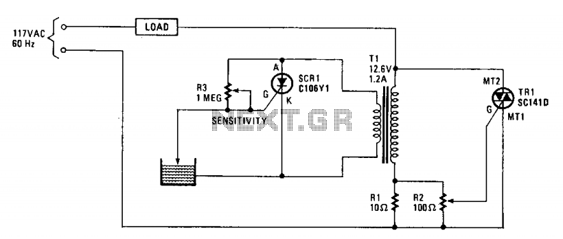
The operation of the circuit is based on the difference in the primary impedance of a transformer when its secondary is loaded compared to when it is open-circuit. The impedance of the primary of T1 and resistor R1 are...
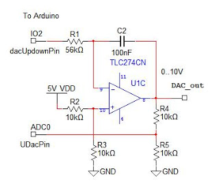
An analog output for Arduino can be achieved using a Digital-to-Analog Converter (DAC), commonly implemented with an R-2R ladder circuit. However, this DAC lacks an output buffer, which would enhance reliability and compatibility with various loads. For optimal performance,...
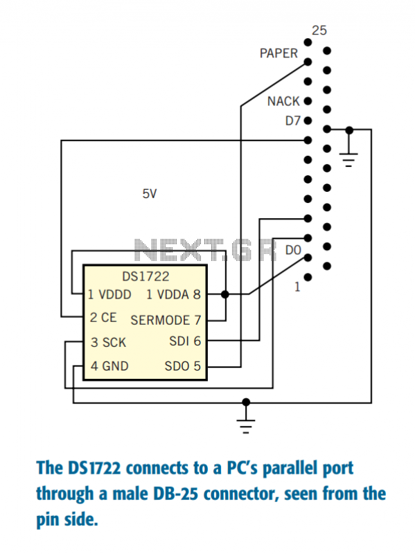
The Dallas Semiconductor DS1722 digital thermometer allows measurement resolution as fine as 0.0625°C in digital form and with linear response. The accuracy specification is only 2°C, but you can improve this figure by careful calibration. Moreover, the accuracy spec...