
Scrolling text in LED dotmatrix display
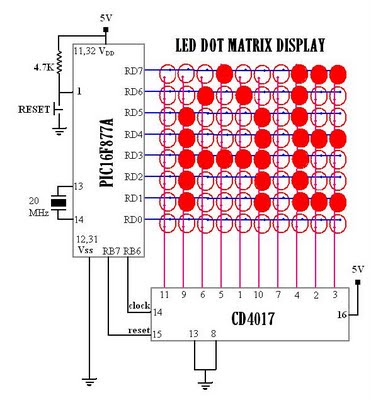
The multiplexed display system operates by leveraging the principle of time-sharing among the display elements. Each LED or pixel is activated in rapid succession, creating the perception of a full display due to the human eye's persistence of vision. The PIC16F877A microcontroller, known for its versatility and ample GPIO (General Purpose Input/Output) pins, serves as the central controller for managing the timing and data output for the display. The CD4017 decade counter facilitates the sequential activation of the columns, responding to clock pulses generated by the microcontroller.
The implementation involves setting up the microcontroller to output the necessary row data while controlling the clock signal that drives the CD4017. The clock signal must be carefully timed to ensure that the display refresh rate is high enough to maintain the illusion of continuity. This typically requires a frame rate of at least 60 Hz, meaning each column must be activated within approximately 16.67 milliseconds.
In practical terms, the circuit design includes connecting the microcontroller's output pins to the rows of the display and the CD4017's output pins to the columns. Resistors may be included in series with the LEDs to limit current and prevent damage. The software running on the PIC16F877A is responsible for managing the timing of the column shifts and outputting the correct data for each row. This is often accomplished using a timer interrupt or a loop that controls the timing based on the system clock frequency.
Overall, this multiplexed display system not only demonstrates effective use of microcontroller capabilities but also showcases the integration of various electronic components to achieve a functional and visually appealing output.Multiplexed displays are electronic displays where the entire display is not driven at one time. Instead, sub-units of the display (typically, rows or columns for a dot matrix display or individual characters for a character orientated display, occasionally individual display elements) are multiplexed, that is, driven one at a time, but the electr onics and the persistence of vision combine to make the viewer believe the entire display is continuously active. In the above figure, the rows are negative and columns are positive. Now, if I connect a single column to positive 3V and a single row to negative (0v), then the LED in place of the intersection of the corresponding row and column will glow.
Now, if we select a single column(means a + volt at selected column), say column 1 and multiple rows (means connect 0V to few selected rows), say row 1, 2 & 8, then the selected 1, 2 and 8 LEDs in column 1 will glow. Now if i shift the column(means shifting the positive voltage from column 1 to column 2), and if i change the row data, then the new data will be displayed in column 2.
Now, if i continuously shift the column and provide row data corresponding to each column, then i can display the different row data (8 bit) in different columns. . So, if one frame(10 column shift) is completed within 1/16 th of a second, then due to the persistence of vision of our eye, we will feel the entire columns are activated at a time, and thus we will see all the ten -8bit data corresponding to the 10 columns, at a time.
In the above circuit, the PIC16F877A provides the 8 bit row data. CD4017 is used to select the column one by one. Now, for shifting the column position, a clock is provided by the PIC to the CD4017. On every clock, the column is shifted. (from right to left in this case). Here, I used a PIC16F877A microcontroller and a CD4017 johnson counter. But the 40 pin PIC16F877A is having more number of PORT pins, and thus there is no need of the CD4017 for this small display, and i could use some other port pins of the PIC to work as a johnson counter. But any way, i used a CD4017 just because, in the same circuit board, i could use other free PORT pins for some other purpose like LCD interfacing, USRT, SPI, PWM etc later.
I am using Hi-Tech C compiler with MPLAB IDE for compiling the embedded C program and thereby generating the hex file which is to be loaded/burned to the PIC. There are many other C compilers, but i started with Hi-Tech C and I like it. So I am continuing with it. /* To display a still letter `F` in the display */ #include
I can rectify th(){scroll(0x01, 0x7D, 0 not a good way. Bett0}, // ; {0x00, 0x08, 0x14, 0x22, 0x00}, // < {0x14, 0x14, 0x14, 0x14, 00x0e, 0x70, 0x00}, // Y 🔗 External reference
Related Circuits
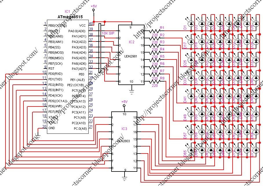
This project involves a scrolling LED display composed of 64 LEDs arranged in a matrix configuration. The anodes of the LEDs are driven by a driver IC, UDN2981, while the cathodes are controlled using the ULN2803. An Atmega8515 microcontroller...
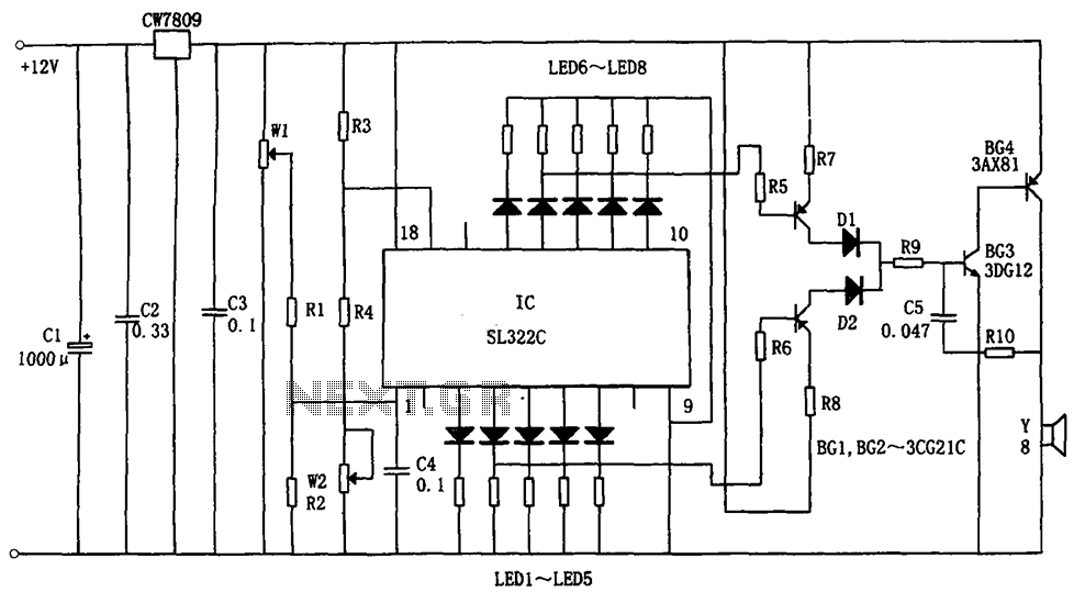
The circuit illustrated in the figure is a hydraulic oil level alarm system for automotive applications. It consists of a light-emitting diode (LED) driver, the SL322C integrated circuit (IC), a voltage regulator circuit (CW7809), and hydraulic oil level sensors...
The LT3465/LT3465A are step-up DC/DC converters designed to drive up to six LEDs in series from a Li-Ion cell. Series connection of the LEDs provides identical LED currents and eliminates the need for ballast resistors. These devices integrate the...
An exhaust fan is a crucial component in kitchens. This document presents a simple circuit designed to control kitchen fans by monitoring the ambient temperature. It is built around... The circuit for controlling an exhaust fan based on ambient temperature...
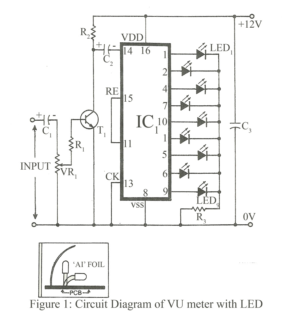
When constructing a stereo amplifier or if one is already owned, it is beneficial to incorporate this circuit. The entire setup is based on the IC4017, with its clock input connected through a BC107 transistor. The IC4017 functions as...
This is a programmable alarm timer circuit that uses LEDs to indicate hours and minutes. Twelve LEDs can be arranged in a circle to represent the 12 hours of a clock face, and an additional 12 LEDs can be...
Warning: include(partials/cookie-banner.php): Failed to open stream: Permission denied in /var/www/html/nextgr/view-circuit.php on line 713
Warning: include(): Failed opening 'partials/cookie-banner.php' for inclusion (include_path='.:/usr/share/php') in /var/www/html/nextgr/view-circuit.php on line 713