
Selective Timer Alarm Circuit With 4060IC
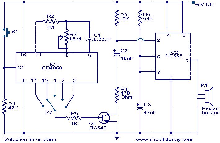
The Selective Timer Alarm Circuit utilizes the 4060 IC, which serves as a versatile timer and oscillator. This IC is particularly advantageous due to its ability to generate a precise time delay, making it suitable for applications requiring timed events. The circuit typically consists of resistors and capacitors that determine the timing interval, which can be adjusted to meet specific requirements.
The operation of the circuit begins when the timer is activated, initiating the oscillation within the 4060 IC. The output of the IC drives an alarm system, such as a buzzer or LED indicator, that signals the user when the timer is active. After the designated time elapses, the 4060 IC automatically disables the output, thereby turning off the alarm. This feature is particularly useful in scenarios where an alert is needed for a limited duration, ensuring that the alarm does not continue indefinitely.
The design of the circuit can be modified to include additional functionalities, such as manual reset options or adjustable timing settings. By varying the resistor and capacitor values, the timing range can be tailored to suit different applications, from simple reminder alarms to more complex timing functions in automated systems. Overall, the Selective Timer Alarm Circuit based on the 4060 IC provides a reliable and efficient solution for timed alert mechanisms in various electronic projects.The following circuit shows about Selective Timer Alarm Circuit. This circuit based on the 4060IC. Features: The alarm will automatically turn OFF after the .. 🔗 External reference
Related Circuits
This circuit is similar to the LED clock using 12 neon indicator lamps instead of LEDs. It operates from 2 high capacity ni-cad cells (2.5 volts) which keep it going for a couple weeks. High voltage (70 volts) for...
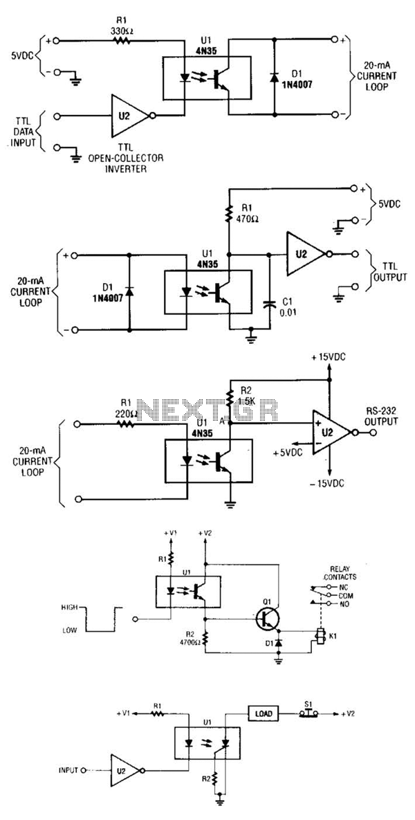
A circuit for isolating a variable resistor is presented. An optoisolator, which consists of an LED and a photo-conductive cell (or photoresistor), is utilized. The current flowing through the LED regulates its brightness, which subsequently dictates the resistance between...
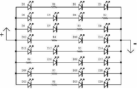
A light-emitting diode (LED) lamp is a solid-state lighting device that utilizes light-emitting diodes as its light source. LEDs are a cost-effective and convenient choice for various lighting applications. They are available in an extensive range of colors, styles,...
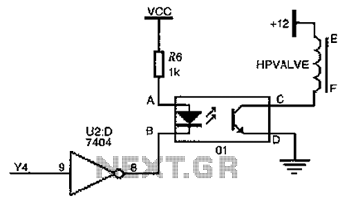
The driver circuit for the high-pressure natural gas shut-off valve utilizes solid-state relays. In dual-fuel mode operation, the fuel switching mechanism is controlled by a logic section that activates Y4 to a high state via U2 (7404 inverters). This...
The circuit consists of a lag comparator with amplifier A1 and an inverting integrator A2. The charging and discharging time constant is determined by the integral resistors (R1 + RP1) and the capacitor C1. Diodes VD1 to VD5 form...
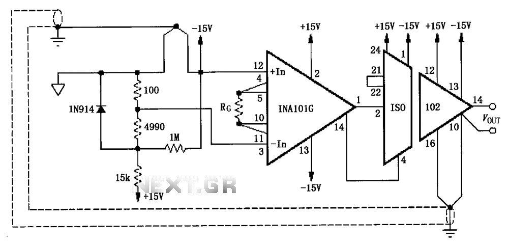
The circuit, as illustrated in the figure, consists of an ISO102 and an INA101 designed to eliminate ground loops and provide high-end cold junction compensation for a thermocouple amplifier. This configuration utilizes a K-type thermocouple to detect temperature at...