
Self-powered Fast Battery-Testers

This battery testing circuit is designed for efficiency and accuracy, enabling quick assessments of battery health without the need for external power sources or expensive equipment. The dual-range functionality allows for versatility in testing various battery types, ensuring that both 3V to 15V batteries and 1.5V cells can be evaluated effectively.
The core of the circuit relies on a constant current output, provided by FET Q1, which ensures that the LED's brightness remains stable across a range of input voltages. This feature is critical for accurate visual feedback during testing. The use of a square wave generator (IC1) and an inverter (IC2) enhances the circuit's ability to multiply voltage, allowing for the effective operation of the load applied to the battery under test.
The design includes protective measures to prevent damage to the circuit from excessive battery discharge. The feedback mechanism involving Q3 and LED D7 serves as a visual indicator of battery performance, providing immediate feedback on the battery's ability to maintain voltage under load. The timing of the feedback, governed by the discharge characteristics of capacitor C8, allows for a brief but informative glimpse into the battery's condition.
In summary, this circuit is a practical solution for rapid battery testing, combining simplicity with effective functionality. It is particularly useful in environments where quick battery assessments are necessary, such as in automotive or portable electronic applications. Its design reflects a balance between performance, cost-effectiveness, and user-friendly operation.This circuit runs a fast battery test without the need of power supply or expensive moving-coil voltmeters. It has two ranges: when SW1 is set as shown in the circuit diagram, the device can test 3V to 15V batteries.
When SW1 is switched to the other position, only 1. 5V cells can be tested. FET Q1 provides a constant current generator biasing LED D1 and Q2 Base. In this manner D1 illuminates at a constant intensity, independent of battery voltage from 3 to 15V and Q2 (when P1 is closed) applies a constant current load of about 120mA to the battery. IC1 is a square wave generator oscillating at about 3KHz. IC2 acts as an inverter and drives, together with IC1 but in anti-phase, Diodes D2-D6 and Capacitors C4-C7, obtaining a voltage multiplication.
C8 is charged by this raised voltage and R8-R10 form a voltage divider biasing the Base of Q3. When P1 is open, a very light load is applied to the battery under test and Q3 Base is biased in order to maintain LED D7 in the off state. Closing P1, a 120mA load is applied to the battery under test. If the battery is not fully charged, its output voltage starts reducing: when this voltage falls 0. 6V below the battery nominal voltage, Q3 Emitter becomes more negative than the Base, transistor is hard biased and D7 illuminates.
Obviously, this state of affairs lasts a few seconds: the time spent by C8 to reduce its initial voltage to the new one, proportional to the voltage of the loaded battery. If the battery under test is in a good charging state, its output voltage did not fall under a 120mA loading current, so LED D7 stays off.
When testing 1. 5V batteries, the circuit formed by Q1, Q2, D1, R1 & R2 doesn`t work well at this supply voltage, so a 150mA load current is applied to the BUT by means of the 10 Ohm resistor R3 after switching SW1A. Q3 bias is also changed via SW1B. 🔗 External reference
Related Circuits

A photodiode can be utilized for high-speed digital transmission; however, it is necessary to provide a high-speed signal conditioner for this purpose. The amplifier circuit... A photodiode is a semiconductor device that converts light into electrical current. In high-speed digital...
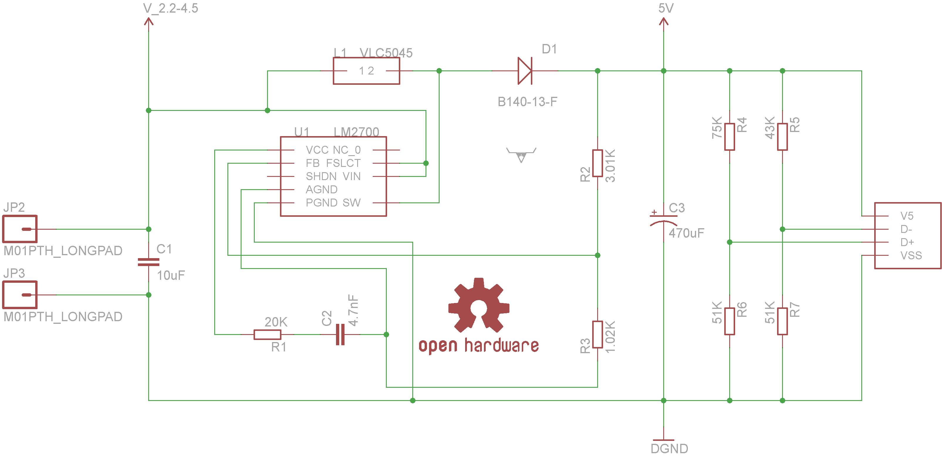
Powered by the LM2700 IC, this charger is capable of recharging devices such as MP3 players, cameras, cell phones, and any other gadgets that can be connected to a USB port at an accelerated rate. The circuit utilizes the LM2700...
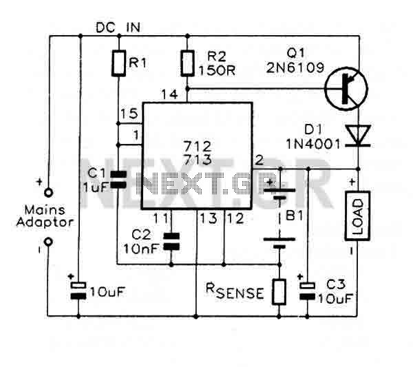
The MAX712 and MAX713 are nickel cadmium (Ni-Cd) battery fast charge controllers that facilitate the rapid charging of batteries from a DC source, which must be at least 1V higher than the maximum battery voltage. These controllers can charge...
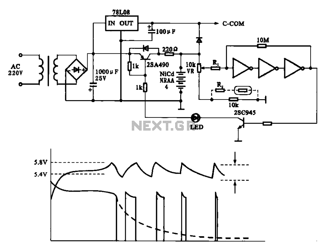
Fast charging circuit that illustrates voltage and current waveforms along with the configuration of the fast charge circuit for the charger. The detection and control circuit consists of three inverters (GMOS) from integrated circuits, enabling automatic control functions. The fast...
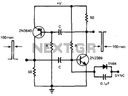
This simple and symmetrical free-running generator has a 50-ohm output impedance, a pulse width of 100 ns, and complementary outputs that swing from ground to the power supply voltage. It operates within a power supply range of less than...
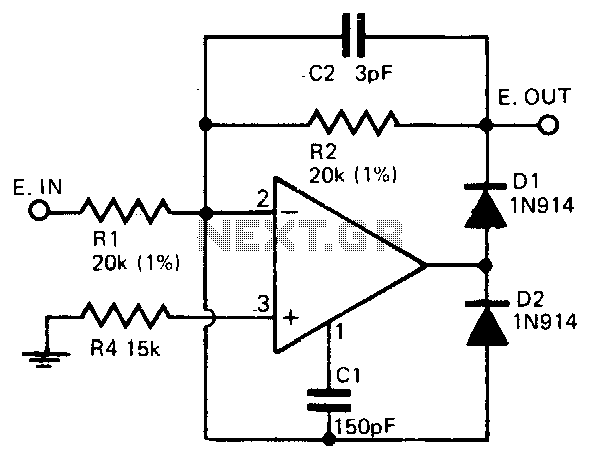
A precision half-wave rectifier utilizing an operational amplifier will achieve a rectification accuracy of 1% from DC to 100 kHz. A precision half-wave rectifier circuit is designed to convert an AC signal into a unidirectional output while maintaining high accuracy...