
Sensitive-field-strength-meter
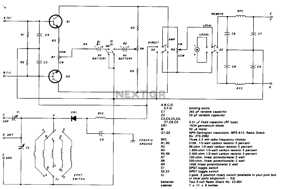
The two-pole, five-position switch, coils, and 365-pF variable capacitor cover a range from 1.5 to 30 MHz. The amplifier uses Darlington npn transistors whose high beta of 5000 provides high sensitivity, with SL used as the amplifier on/off switch. Switch S2 in the left position allows the output of the 1N34 diode to be fed directly into the 50-µ meter (M) for direct reading. When S2 is in the right position, the amplifier is switched into the circuit. Switch S3 is for local or remote monitoring. At full gain setting, the input signal is adjusted to give a full-scale reading of 50 mA on the meter. Then, with the amplifier switched out of the circuit, the meter reading drops down to about 0.5 mA. A 2.5-mH RF choke and capacitors C3, C4, and C5 effectively keep RF out of the amplifier circuit.
The circuit incorporates a two-pole, five-position switch that allows for versatile operation across a frequency range of 1.5 to 30 MHz, facilitated by a 365-pF variable capacitor. The amplifier section utilizes Darlington npn transistors, which are known for their high current gain, with a beta value of 5000. This configuration enhances the sensitivity of the circuit, making it suitable for various applications that require precise signal amplification.
The SL switch functions as the on/off control for the amplifier, enabling the user to engage or disengage the amplification as needed. The second switch, S2, provides a choice between direct measurement and amplified output. In the left position, the output from the 1N34 diode is routed directly to a 50-µA meter, allowing for immediate analog readings of the detected signal. When S2 is switched to the right, the amplifier is activated, providing a boosted signal to the meter for enhanced readability.
Additionally, S3 serves as a selector for local versus remote monitoring, adding flexibility to the system's operation. The circuit is designed to ensure that, at maximum gain, the input signal is calibrated to yield a full-scale deflection of 50 mA on the meter, indicating optimal performance. Conversely, when the amplifier is bypassed, the meter reading reduces to approximately 0.5 mA, reflecting the low-level signal without amplification.
To mitigate interference and maintain signal integrity, the design incorporates a 2.5-mH RF choke along with capacitors C3, C4, and C5. These components work in tandem to filter out unwanted RF signals, ensuring that the amplifier operates within its intended frequency range without degradation from external RF noise. This configuration is critical for applications requiring high fidelity and precision in electronic measurement and monitoring systems.The two-pole, five-position switch, coils and 365-pF variable capacitor cover a range from 1.5 to 30 MHz. The amplifier uses Darlington npn transistors whose high beta, 5000, provides high sensitivity with Sl used as the amplifier on/off switch.
Switch S2 in the left position allows the output of the 1N34 diode to be fed directly into the 50-,u meter (M) for direct reading. When S2 is in the right position, the amplifier is switched into the circuit. Switch S3 is for local or remote monitoring. At full gain setting, the input signal is adjusted to give a full-scale reading of 50 mA on the meter. Then with the amplifier switched out of the circuit, the meter reading drops down to about 0.5 mA. A 2.5-mH rf choke and capacitors C3, C4, and C5 effectively keep rf out of the amplifier circuit. 🔗 External reference