
Sensitive IR Switch Circuit
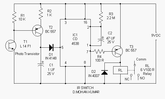
The ultra-sensitive IR receiver circuit is engineered to detect infrared signals emitted from an IR transmitter, enabling the control of AC devices with precision. The core component of this circuit is a phototransistor, which responds to the IR light and converts it into an electrical signal.
The circuit typically includes a few key components: a phototransistor, a resistor, a capacitor, and a relay. The phototransistor is positioned to receive the IR signals. When the IR transmitter is activated, the phototransistor detects the incoming IR light, causing it to conduct and allowing current to flow through the circuit.
In a typical configuration, the output from the phototransistor is connected to the base of a transistor or to a microcontroller, which acts as a switch to control the relay. The relay, in turn, can be used to switch on or off the connected AC devices. A resistor is often included in the circuit to limit the current flowing through the phototransistor and protect it from damage. Additionally, a capacitor may be used to filter out noise and stabilize the signal.
The sensitivity of the circuit can be adjusted by changing the values of the components, particularly the resistor and capacitor. This allows for flexibility in applications, accommodating various distances and lighting conditions. The circuit can be powered by a standard DC power supply, ensuring compatibility with most household AC devices.
Overall, this ultra-sensitive IR receiver circuit provides a reliable solution for remote control applications, enhancing convenience in managing AC devices.Here is the circuit of an ultra sensitive IR receiver that can be used to switch on various AC devices through an IR transmitter. It uses the Photo transis.. 🔗 External reference
Related Circuits
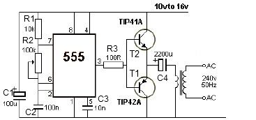
12V power inverter circuit utilizing a 555 timer for an electronic project. The 12V power inverter circuit is designed to convert a DC voltage of 12 volts into an AC voltage suitable for powering small electronic devices. The core component...
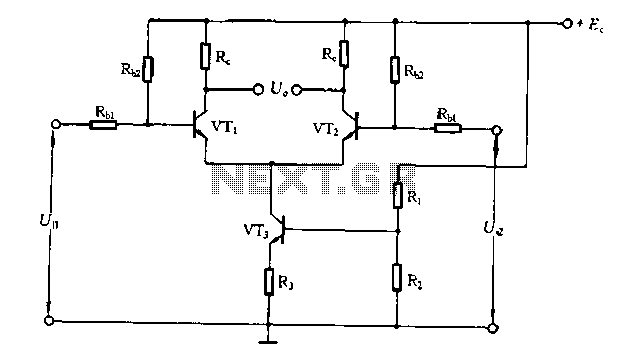
The differential amplifier circuit features a constant current source. The differential amplifier is a fundamental building block in analog electronics, utilized for amplifying the difference between two input voltages while rejecting any signals that are common to both inputs. Central...
Speaker relay delay controlling circuit for audio amplifier The speaker relay delay controlling circuit is designed to manage the connection of speakers to an audio amplifier, ensuring that the speakers are activated only after a specified delay. This delay serves...
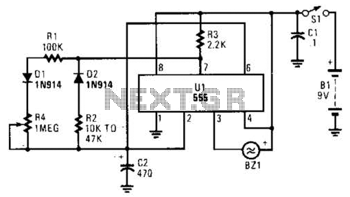
This timer circuit utilizes a 555 IC timer in conjunction with three 74LS193 counters to control an LED display. The circuit is activated by one individual who turns on the piezo buzzer BZ1 through Q1, simultaneously starting the timer....
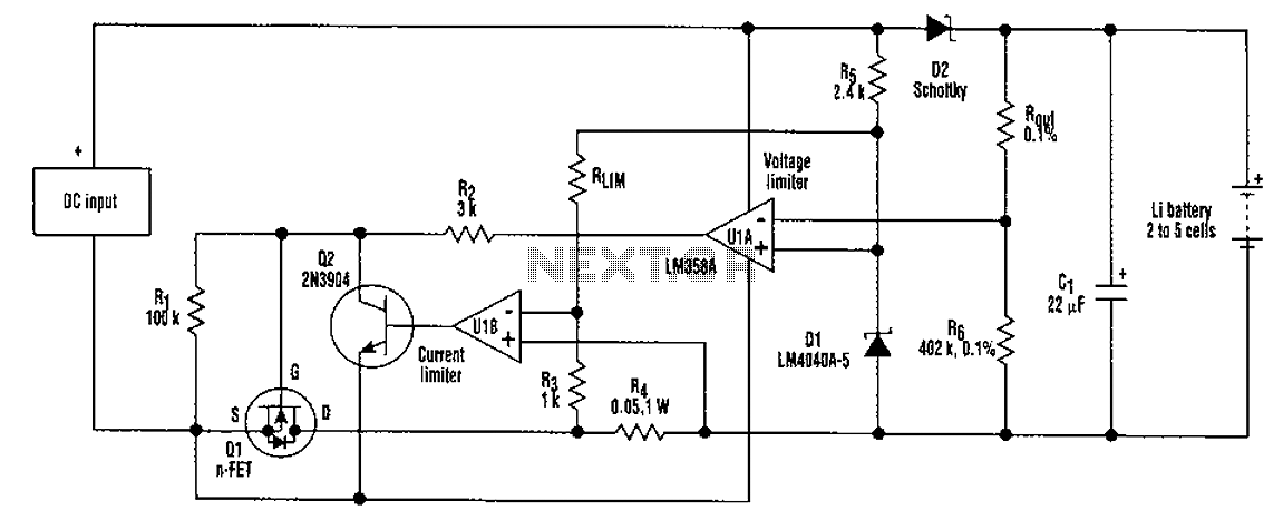
A universal rechargeable lithium battery circuit design, applicable to different battery types and numbers of batteries. This is because both the charger output voltage or current limit setpoint and the maximum charging current can be adjusted by simply changing...
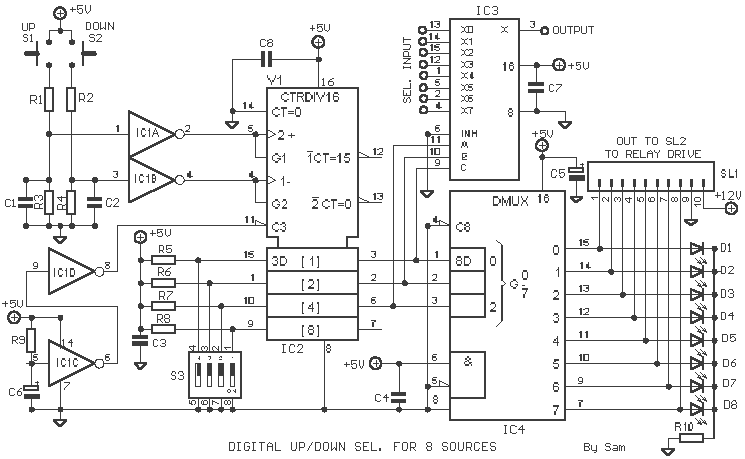
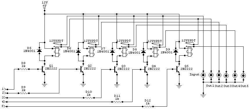
As with the Electronic sel. 8 we also have here a circuit with a choice of 8 different sources. The difference is that only two of the switches are used and the movement of commands is Up-Down in series....
Warning: include(partials/cookie-banner.php): Failed to open stream: Permission denied in /var/www/html/nextgr/view-circuit.php on line 713
Warning: include(): Failed opening 'partials/cookie-banner.php' for inclusion (include_path='.:/usr/share/php') in /var/www/html/nextgr/view-circuit.php on line 713