
sequencer circuit
The circuit design incorporates a sequencer board powered by a 12V source, which manages multiple relays for controlling coaxial relays, a preamplifier, and an amplifier. The sequencer board contains DIL relays that are exclusively responsible for operating external relays, ensuring the system's modularity and flexibility. The inclusion of additional relays on the board accommodates various operational requirements across different EME station configurations, enhancing compatibility with other setups.
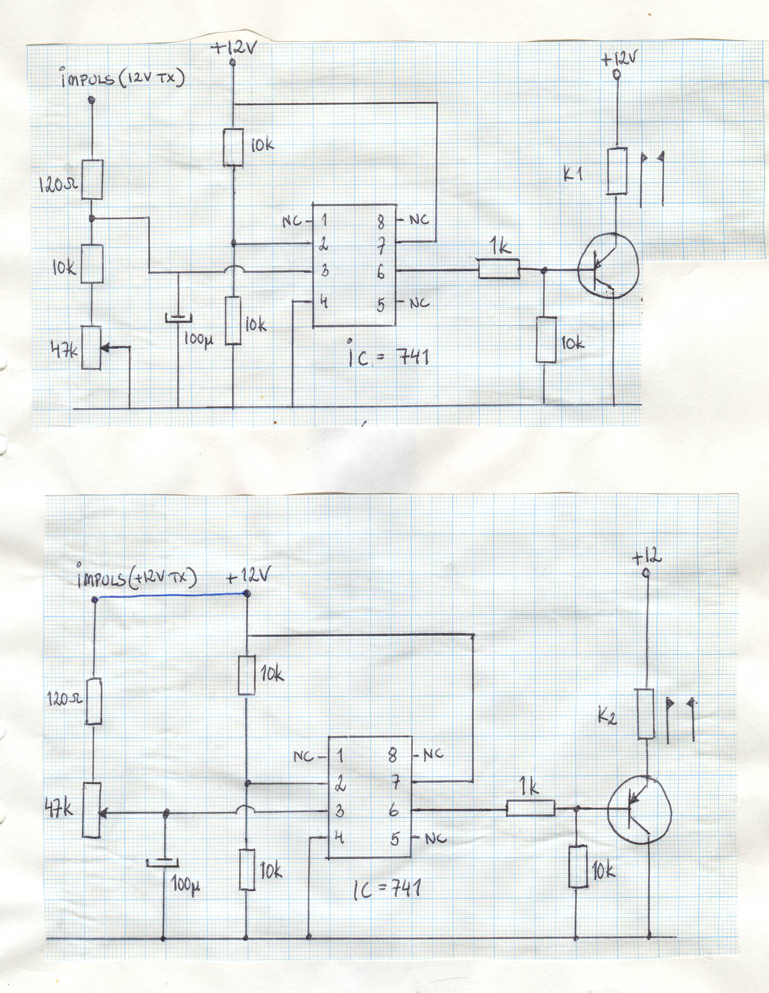
In the context of the 432/1296 station, the sequencer board is capable of switching between 12V and 24V, which allows for the utilization of all available relays. The circuit diagram illustrates the utilization of operational amplifiers (741) for specific relay control functions. One operational amplifier manages the antenna relay, incorporating a delay on break feature to prevent any RF interference during the transition from transmit to receive mode. This feature is critical in maintaining signal integrity and preventing unwanted transmission during switching.
The second operational amplifier is dedicated to controlling the keying of an external amplifier, with an immediate break function that ceases operation of the transmitter/amplifier when necessary. This immediate response is crucial for protecting the equipment and ensuring proper operational sequencing.
The sequencer is integrated with the CAT/Tuner connector of the FT-897, with the TX ground utilized to activate the sequencer through a DIL relay. The operational amplifiers are triggered by a positive 12V impulse, ensuring that the sequencing process is initiated correctly. Additionally, the circuit routes a +13.8V supply from the same connector through a 1.5k resistor to relay contacts that control the external amplifier, returning to the TX Inhibit pin. This configuration ensures that when the TX Inhibit pin is held high, RF transmission is completely disabled across all bands, thereby safeguarding the system against accidental RF emissions.
This design effectively prevents RF transmission from the FT-897 until the sequencer is properly engaged, ensuring that the antenna relays are activated before any RF is transmitted. The reliability of this setup has been demonstrated, as there have been no incidents of preamplifier damage attributed to sequencer malfunction, showcasing the robustness of the design.I am feeding that box with 12 volts, and it has a sequencer board, some external relays to drive the coaxial relays, preamp and the amplifier. As you can see, this sequencer board has some DIL relays, they are only intended to drive external relays that actually control all of the above.
There are indeed more relays on that board than needed, but the boards are "generic" and I use similar boards in other placesof my EME station. The one I use for my 432/1296 station switches both 12V and 24V, and then I make use of all relays on the board. As you see in the circuit diagram, one 741 is for activating the antenna relay, with a delay on break to make sure there is no RFwhen switching back to receive.
The other741 is for delaying the keyingofan external amplifier, and it has instant break to stop the transmitter/amplifier. The sequencer is connected to the CAT/Tuner connector on the back of the FT-897. I use the TX Gnd to activate the sequencer via a DIL relay on the sequencer board. Remember, the sequencer 741`s are triggered by a +12V impulse. I also route the +13. 8V available on the same connector, via a 1. 5k resistor, to a set of contacts on the relay that keyes the external amplifier and then back to the pin TX Inhibit.
When this pin is held high, no RF comes out of the radio on any band. This way, no RF can be transmitted from the FT-897 before the amplifier is keyed, and this also makes sure that the antenna relays are engaged properly. Actually, no RF is coming out of the FT-897 unless the sequencer is actually keyed properly, which has proven to be fool proof, so far.
It might look and sound complicated, but it is not. describing it in words is complicated. No preamp has ever been blown because of sequencer failure. so far. 🔗 External reference
Related Circuits
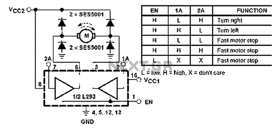
All inputs are compatible with TTL. Each output consists of a complete totem pole driver circuit, utilizing Darlington transistors and pseudo-Darlington sources. The driver enable signals, labeled as 1,2 EN and 3,4 EN, control the activation of drivers 1...
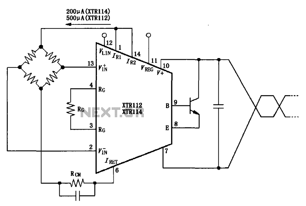
The two current sources within the chip (1 foot and 14 feet out) provide excitation. The output of each current source is 0.2 mA (XTR114) or 0.5 A (XTR112). The common mode input voltage is adjustable, ranging from 1.25...
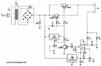
This battery charger circuit is regulated and adjustable, enabling it to charge most NiCAD batteries. It can accommodate both single cells and multiple battery cells connected in series or parallel. The maximum voltage of the batteries should not exceed...
This circuit requires physical connections to be made to the computer's serial port (COM1 or COM2). It is generally considered difficult to cause harm to oneself or the computer through improper connections to this port; however, there is no...

The TEA5551T monolithic integrated radio circuit can be utilized to design an AM radio receiver circuit intended for portable use with headphones. This circuit incorporates all necessary components for a complete AM radio receiver, including a fully integrated AM...

This voltmeter utilizes a pair of JFETs in a balanced-bridge source-follower amplifier circuit. Q1 and Q2 should be matched within 10% for IDSS. This configuration minimizes meter drift and maintains bridge balance over temperature. The described voltmeter is an advanced...