
Sequential flasher
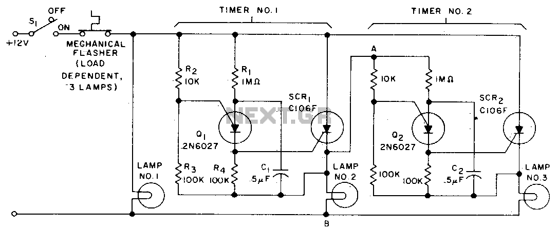
This circuit operates as a turn signal flasher system utilizing a combination of transistors and silicon-controlled rectifiers (SCRs) to control the activation of multiple lamps in a sequential manner. The initial activation is initiated by closing the turn signal switch (SI), which causes lamp #1 to illuminate. Concurrently, capacitor C1 begins to charge, and its voltage rise is monitored by transistor Q1. When the voltage across C1 reaches a threshold that exceeds the gate voltage of Q1, Q1 enters a low resistance state, effectively allowing current to flow through the circuit.
Upon activation of Q1, SCR1 is triggered, leading to the illumination of lamp #2 and the commencement of a second timing circuit. This timing circuit may include additional components such as resistors or capacitors that determine the timing characteristics for the sequential operation of the lamps. As Q2 transitions into a low resistance state following the activation of the timing circuit, SCR2 is subsequently triggered, resulting in the illumination of lamp #3.
The thermal flasher component of the circuit plays a crucial role in controlling the overall operation. It periodically interrupts the current flowing to all three lamps, which leads to the commutation of SCR1 and SCR2. This interruption resets the circuit, allowing it to prepare for the next activation cycle. The design ensures that the lamps operate in a coordinated manner, providing a clear visual indication during signaling while also incorporating a timing mechanism that prevents simultaneous activation, thereby enhancing safety and functionality in automotive applications.When the turn signal switch SI is closed, lamp #1 will be activated and capacitor Cl will charge to the triggered voltage of Ql. As soon as the anode voltage on Ql exceeds its gate voltage by 0 V, Ql will switch into the low resistance mode, thereby triggering SCR1 to activate lamp #2 and the second timing circuit.
After Q2 switches into the low resistance state, SCR2 will be triggered to activate lamp #3 When the thermal flasher interrupts the current to all three lamps, SCR1 and SCR2 are commutated and the circuit is ready for another cycle. 🔗 External reference
Related Circuits

Standard LED flashers activate the LED in a rapid on-off sequence, which can become bothersome over time. The circuit presented here offers a more gradual illumination effect. This circuit utilizes a simple design to create a soft flashing LED effect,...
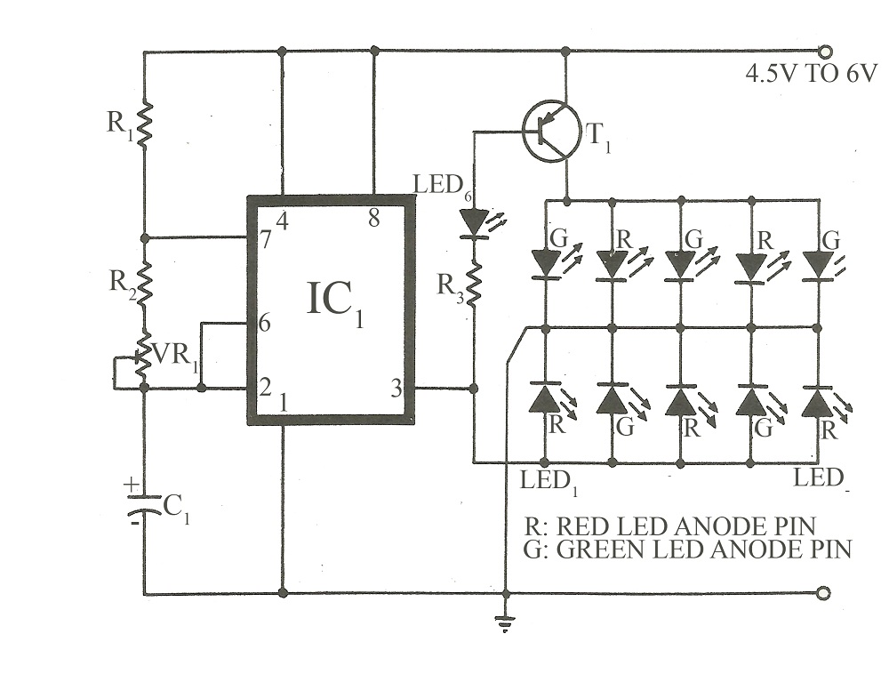
This circuit is similar to various published flasher circuits that utilize the IC 555 as a free-running multivibrator. The primary distinction is in the method of flashing bi-color LEDs. When the output at pin 3 of the IC 555...
For motorcycle or scooter riders, it is common to forget to deactivate the flashing indicators after making a turn, especially in the absence of an audible reminder. The circuit for an automatic turn signal cancellation system is designed to address...
More: A comprehensive electronic schematic typically includes various components such as resistors, capacitors, diodes, transistors, and integrated circuits, interconnected to perform specific functions. Each component is represented by standardized symbols, and their values are indicated alongside or...

The concept of this economical flashing LED indicator is straightforward. It employs a low-frequency oscillator to drive two LEDs connected in anti-parallel. In the circuit diagram, it can be observed that the current flows for a brief duration with...
I have received several emails asking how to connect up some lights so that when the phone rings, they flash. This is very useful in a situation where there is lots of noise and it is impossible to hear...