
Sequential Flasher

The circuit utilizes a 555 timer configured in astable mode to generate a square wave output. This output serves as the clock signal for the CMOS counter, which counts the pulses produced by the 555 timer. The RCA CA3079 zero-voltage switch is employed to control the operation of the triacs, which in turn manage the power delivered to the connected loads, such as lamps. The triacs TR1 through TR4 are arranged in a manner that allows for sequential activation, enabling various lamp display patterns.
The circuit design should ensure that the 555 timer is powered adequately, typically operating at a voltage between 4.5V and 15V, while the CMOS counter should be selected based on the required counting capacity and voltage compatibility. The CA3079, designed for switching applications, provides the necessary isolation and control for the high voltage line, ensuring that the low-voltage components of the timer and counter are protected.
To implement this circuit safely, it is crucial to use components rated for the voltages involved, particularly the CA3079 and the triacs, which must handle the 117-V AC line. Proper insulation of all connections, especially those interfacing with high voltage, is essential to prevent accidental electric shock or circuit failure. Additionally, using heat sinks with the triacs may be necessary to dissipate heat generated during operation, ensuring reliability and longevity of the components.
Overall, this circuit exemplifies a practical application of timer and counter technology in controlling high-voltage loads, suitable for decorative lighting and similar uses, while emphasizing the importance of safety in high-voltage electronics. Using a 555 timer to drive a CMOS counter, this device uses RCA CA3079 zero-voltage switch to control triacs TR1 through TR4. This circuit can be used to sequence lamp displays, etc. Caution: The CA3079s are connected to the 117-V line, as is the clock and counter circuit and their power supplies. Use caution, good insulation, and safe construction practices. 🔗 External reference
Related Circuits
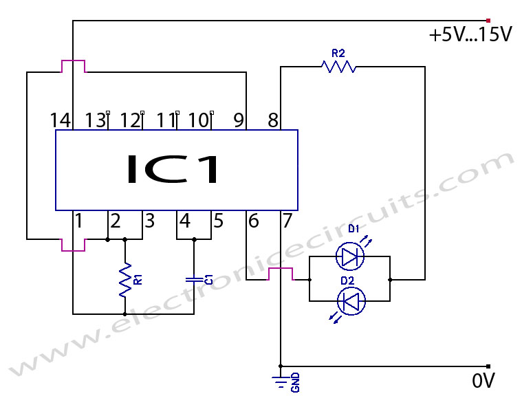
Two LED CMOS Flasher Circuit Diagram. This is a simple two LED CMOS robot (flasher, multivibrator) circuit using CD4069 six inverters. The two LED CMOS flasher circuit utilizes the CD4069 integrated circuit, which contains six inverters, to create a multivibrator...
This circuit utilizes the TLC555CP timer integrated circuit to flash an LED approximately twice per second. This specific 555 timer operates on a voltage of only 3 volts, allowing it to be powered by two 1.5-volt cells. When using...
A compact and intriguing circuit designed to flash automotive headlights. It utilizes a well-known NE555 timer circuit to achieve this functionality. The circuit operates by employing the NE555 timer in astable mode, which allows it to generate a continuous square...

Flashing occurs each time the capacitor discharges through the turned-on SCR. When the discharge current falls below the SCR holding current, the SCR turns off, and the capacitor begins charging for another cycle. The circuit will maintain a slower...
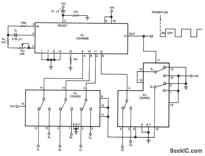
The timer circuit provides independent control of the output's on and off intervals, which can range from 0.055 seconds to 30 minutes, with minimal impact from power-line transients. IC1 is a CMOS programmable timer chip that features 24 ripple-binary...
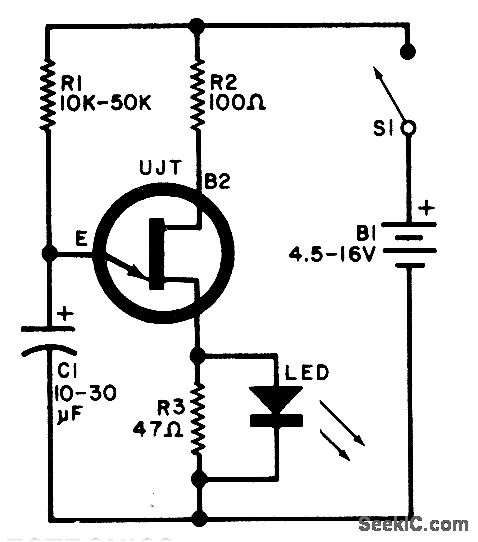
A relaxation oscillator is employed to flash an LED in the base circuit. Capacitor C1 is charged gradually through resistor R1 by the power supply and is then discharged intermittently through resistor R3 and the LED by the Unijunction...