
SERIAL to USB Home Made Using ATmega8
The USB to Serial Converter circuit based on the ATmega8 microcontroller is a versatile tool for interfacing USB devices with serial communication protocols. The ATmega8 serves as the core processing unit, executing the firmware that implements the USB communication stack. The connection of the D+ and D- lines to PB0 and PB1 is critical for maintaining the integrity of high-speed data transfers, ensuring that both the USB host and the connected serial device can communicate effectively.
The inclusion of a 1.5k Ohm pull-up resistor on the data lines is a standard practice in USB designs, allowing the ATmega8 to operate at a low-speed data rate, which is essential for maintaining signal quality and minimizing data loss. Other passive components, such as decoupling capacitors and an oscillator, play a vital role in ensuring stable operation by filtering out noise from the power supply and providing a reliable clock signal for the microcontroller.
For applications requiring RS-232 communication, the addition of the MAX 232 IC is necessary. This component translates the TTL logic levels from the ATmega8 to the RS-232 voltage levels required by many traditional serial devices. The design can easily be adapted for various applications, including LED control, by simply connecting the output pins to the desired load through appropriate current-limiting resistors.
The firmware's architecture is designed to handle USB data reception efficiently. It captures incoming data packets, identifies the synchronization pattern, and processes the packets by checking for the end of transmission signal. This modular approach allows for easy modifications and enhancements, enabling users to tailor the firmware to specific application needs, such as adding custom functions or supporting additional communication protocols.
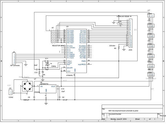
Overall, the USB to Serial Converter with the ATmega8 microcontroller provides a flexible and efficient solution for bridging USB and serial communication interfaces, making it suitable for a wide range of electronic projects and applications.Make a USB to Serial Converter own with ATmega8 microcontroller. In this ATmega8 will be given free firmware source code and can be downloaded at the bottom. Because the ATmega8 there is no facility for communication with the USB, then inevitably the data with the USB communication protocol must be made on the firmware itself. For a study guide the USB protocol can be seen in other parts of this website or click the link below to view it. In the firmware can be downloaded existing code to handle USB protocol, so that can be directly used, but if you want to add another facility, you can edit the firmware. The firmware provided is written in assembler language that can be done and compiled with AVR Studio 4.
In addition to code Assemblernya also included his Hexa code compilation results of AVR Studio 4 which can be directly entered in his IC. Here is a circuit schematic drawing USB to Serial converter with ATmega8. USB data line of D + and D-connected to PB0 and PB1 in the ATmega8, this connection should not be changed because of these pins can be done with high-speed data transfer.
For there was a connection and the opinion of a good signal between USB and devices, then ATmega8 be hired at Low Speed data rate that is the way her pull-up 1k5 Ohm resistor on the D-line data. For the other components are only used as a complement for the system to beropersai with good, for example Xtall used as a clock and used as a filter capacitor power supply.
If at this circuit you want a USB to RS-232 converter then you need to add the IC MAX 232 as Level converter from TTL to RS232 levels. If you only want to use to control the LED you can directly connect to the PIN I / O directly in series with a resistor before.
For the implementation of the firmware as the USB receiver and coding of protocolnya, will receive all the packets of data from USB and then stored in an internal buffer. Starting from the first revenues derived from external interrupt (INT0) is the data to "sync pattern", during the admissions process only the last packet in the check the signal EOP (End of Packet).
After the admissions process successfully, the next firmware will mong-coding a number of data packets it receives and then analyze it. Once again because of the USB protocol is very difficult you can read again the USB protocol on the following links.
The process of receiving data on a USB in general can be seen in the following flowchart flow. Firmware is generally divided into several sections main blocks, namely: Users can add the function of certain functions into the firmware, like the function to create a "Customer-Specific", function to "Direct Pin Control" and so forth. To complete the firmware can be downloaded at the bottom. For ATmega8 that will be used the following support for 800-byte FIFO buffer, with baudrate baudrate 300 to 115 200, databit (5, 6, 7, 8), stopbit (1.
2), and its parity (none, odd, even, mark, space). * With the program memory space that is still large, the user can add other facilities such as for USB to I2C converter or USB to Serial PS2 and converter - converter to another. 🔗 External reference
Related Circuits
The TV transmitter presented generates a stream containing four TV programs and broadcasts it on a frequency compliant with the DTT standard. It is suitable for integration into an antenna system and can utilize audiovisual channels generated on-site or...

The circuit depicted in this schematic diagram is a square-wave oscillator circuit. The primary component of this oscillator circuit is the LP165/365 comparator. The square-wave oscillator circuit utilizes the LP165/365 comparator to generate a continuous square wave output. The...
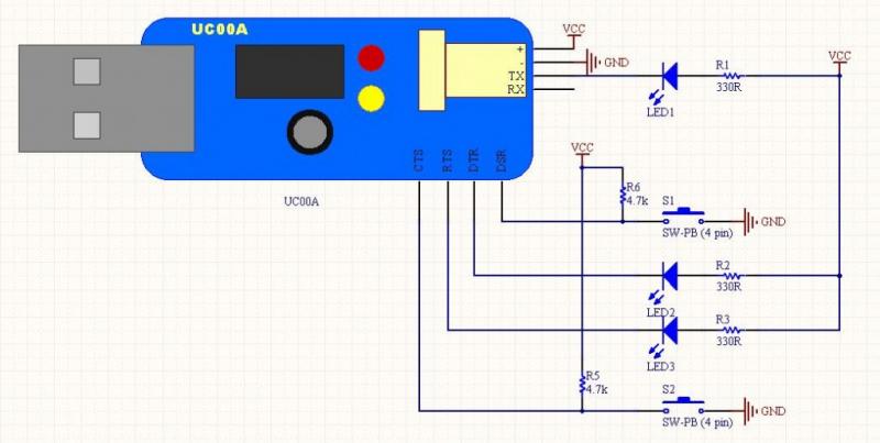
The LEDs operate in an active-low configuration (0), while the initial state of the switches is high (1). In other words, the PC software must send a low signal (0) to activate the LEDs, and if a low signal...
This is a short-range light barrier designed for use as an intruder alarm in doorposts and similar applications. The 555 timer in the transmitter oscillates at approximately 4.5 kHz. The short-range light barrier operates by utilizing a transmitter and a...
DTMF-based Robo Car design using the 8051 microcontroller project. This project demonstrates a method to control a domestic system using the DTMF tone generated by a telephone instrument when the user presses the keypad buttons of a mobile phone...
A pulse width modulator generates a PWM signal, which consists of pulses with a constant frequency while the duty cycle varies according to a modulating signal. A pulse width modulator (PWM) is an essential component in various electronic applications, particularly...