
Servo-Checker JR / Futaba
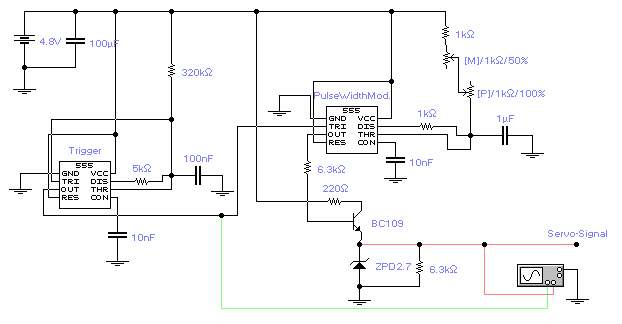
The first timer IC555 generates a negative trigger signal with a frequency of approximately 45Hz, producing a trigger impulse every 22ms. It is important not to exceed 50Hz for optimal servo performance. The second timer IC555 produces a modulated positive square signal with pulse widths ranging from 0.9ms to 2.1ms every 22ms, a technique known as pulse width modulation (PWM). This modulated pulse width conveys the precise servo position, allowing for a total swing of 140-160 degrees of the servo head. A trimmer, labeled M, is used to adjust the middle position, which corresponds to a default pulse width of 1.5ms. The primary input for servo control is a potentiometer, denoted as P, which varies the pulse width from 1.0ms to 2.0ms. It is important to note that the servo requires a significant instantaneous current, which may lead to power supply fluctuations. Therefore, it is essential to include adequate capacitors to maintain supply voltage stability, specifically at least 100nF and 10µF. Insufficient capacitance can cause slight variations in the pulse width, resulting in jerky movements of the servo. The two markers on the screen are spaced 22.5ms apart, with the first pulse measuring approximately 1.0ms in width and the second pulse approximately 2.0ms.
The circuit employs two 555 timer ICs configured in astable and monostable modes to control the operation of a servo motor through pulse width modulation. The first IC555 operates in astable mode, generating a continuous negative trigger signal at the specified frequency. This signal serves as the clock for the second IC555, which is set up in monostable mode to produce a PWM signal. The output of the second IC555 modulates the width of the positive square wave based on the input from the potentiometer P.
The trimmer M is critical for fine-tuning the default pulse width to ensure the servo motor maintains its center position. The PWM technique allows for precise control over the servo's angular position, with a range of 140-160 degrees, which is essential for applications requiring accurate positioning.
To ensure reliable operation, particularly under varying load conditions, the power supply circuit must be designed with sufficient decoupling capacitors. The recommended values of 100nF and 10µF should be placed close to the power pins of the timer ICs to mitigate any voltage dips caused by the servo's current draw. This precaution helps maintain stable operation of the timer circuits, preventing erratic behavior and ensuring smooth servo movements.
The timing characteristics of the PWM signal can be visually represented on an oscilloscope, where the first pulse width can be observed at approximately 1.0ms and the second pulse width at approximately 2.0ms, with a consistent period of 22ms between the two. This setup is vital for applications in robotics, remote control systems, and other fields where precise control of servo motors is required.The first timer IC555 creates a negative trigger signal of approximately 45Hz (a trigger impulse every 22ms, DO NOT exceed 50Hz for proper servo function). The second timer IC555 modulates a positive square signal from 0. 9ms to 2. 1ms every 22ms, a method commonly known as pulse width modulation (PWM). The modulated pulse width provides the full in formation for the exact servo position, and allows a total swing of 140-160degrees of the servo head (see pictures below). M is a trimmer to adjust the middle-position (the default pulse width of 1. 5ms), the main input for the servo control is the potentiometer P, which modulates the pulse width from 1.
0ms to 2. 0ms. Note: Since the servo draws quite some instantaneous current (what might cause some power supply droops), ensure that there are sufficient capacitors to support the supply voltage (at least 100nF & 10uF). Otherwise the power supply droops slightly affect the timer circuitry: the pulse width may temporarily vary slightly, resulting in temporarily jerky servo movements.
The two markers are 22. 5ms apart (T2-T1), the first pulse on the screen has a width of approximately 1. 0ms, the second one a width of approximately 2. 0ms. 🔗 External reference