
Servo Driver

The connection of the three potentiometer terminals is vital for the proper functioning of the servo motor. When setting up the circuit, it is important to identify the correct orientation of the potentiometer tags to avoid issues with servo response. The potentiometer configuration typically consists of three terminals: A, B, and C, where Pot B serves as the wiper and is always positioned in the middle. The connections to the servo motor should adhere to the polarity indicated on the motor housing, with the positive connection marked by a red dot.
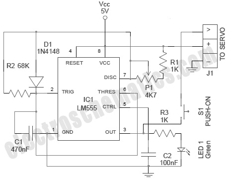
In addition to ensuring correct wiring, it is crucial to inspect the PCB for any potential solder bridges that could lead to short circuits. Utilizing a multimeter to check resistance on the PCB can help identify any unintended connections. The schematic diagram serves as a valuable reference for verifying the interconnections among components, ensuring that the circuit operates as intended.
The removal of the servo drive gears is an essential step in maintaining the integrity of the servo during setup. Documenting the arrangement of the gears can facilitate reassembly and prevent confusion. The use of a battery pack to test the servo's functionality before connecting it to the receiver can help diagnose any issues early in the process. Ensuring correct polarity during this test is critical for avoiding damage to the components.
Once the servo is connected to the receiver, activating the transmitter should prompt the servo to respond appropriately. If the servo does not behave as expected, troubleshooting steps should be taken to check for proper connections and component functionality. The behavior of the servo, such as whether it rotates slightly or fully to one side, provides insight into the correctness of the setup. If adjustments are needed, particularly with the potentiometer connections, they should be made carefully to restore proper operation.
The described procedure emphasizes the importance of methodical assembly, thorough testing, and careful observation of component behavior to ensure the successful operation of the servo motor in the intended application.To hook up the three Pot connections you will firstly need to establish the tags and the positions that I refer to. If you take the pot and look at the back of it, then make sure that the tags are at the top of the pot, then; The only thing that will happen if you get them wrong is that the servo will not respond correctly to your commands and when you power
it up it will wind all the way to one side and stay there. If this happens then reverse the connections to Pot A and C and all should be fine. Pot B is always the middle. To hook up the motor + and -, you simply need to look at the back of the servo motor and there will be a red dot on the positive side. Hook this to the Mot + and the other to the Mot -. Some servo`s have and additional capacitor across the terminals of the servo motor, you can remove this if you want, the circuit has a capacitor on the PCB to do the same job.
Now check that you have not soldered over the tracks and that all components are in the correct spot. Also use a Multi-Meter set at a low Ohmage and test on the backside on the PCB to make sure nothing is shorted out.
You can use the schematic as a guide to which parts of the circuit should be connected to which other parts. Remove all servo drive gears from the servo, making a note of how they came off and where they fit (take a photo if you have a digital camera).
This should only leave the drive gear from the Servo Motor and the pot shaft left in the servo. Take a spare battery pack and through a connect it directly to the servo. You will need and adapter to do this, I just use short bits of left over wire from the resistors to make the bridge. Please make sure you have the polarity right i. e. ; Black servo wire to the negative side of the battery and the Positive Servo wire to the positive side of the battery.
If all is correct the servo should spin a little and then stop. If this does not happen double check every thing again and if it still does not happen, check the signal wire from the servo to make sure there is no voltage on it. If there is you have a problem and you need to check again. If not then you should be safe to plug it into the receiver, as some servo`s don`t spin when you hook them to the battery.
If all is ok then unplug the battery and plug the servo into the receiver and then plug the battery in. If nothing happens except a little spin of the motor then all is fine so far. If something else happens, go back and check again. Now turn on your Transmitter, the servo should start to spin immediately, if it does not turn the output gear all the way in one direction.
If the servo starts to spin, all is well, if not then unplug every thing and check again. You will find that if you turn the output gear from right to left, there should be a spot in about the middle that the servo slows down and it should stop. If it does this you have done a great job as this is what should happen. If it does not then you need to go back and check again. If all is ok then you can re-assemble the servo putting all gears back into place and placing the circuit board into the servo case.
Make sure that the components on the PCB do not cause the connections to the pot to short out etc. If it does then plug it into the Receiver and attach the power to the receiver, it should move, if it does good, if it does not then check again to make sure every thing is ok. If the servo moves a little and stops, this is good. If it moves all the way around to one side and stops, this is bad. If it does this then the wires on the pot are on the wrong way, you will need to reverse Pot A and Pot C.
If all is ok then move the stick for the channel that the servo is plugged into. it should move and operate normally. if it does not then you have to go back and check. I have repaired 6 servo`s this way and they all work and are still working (over 6 months). I would suggest that you take several precautions when 🔗 External reference
Related Circuits
A modified version of the previous program allows control of multiple servomotors, utilizing all available I/O lines on port B. The following listing demonstrates the control of two servos similarly to how a single servo was managed in the...
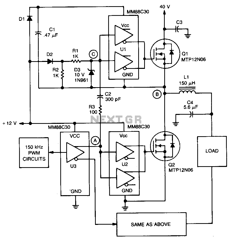
A significant feature of the PWM servo amplifier is the removal of a pulse transformer. A 150 kHz pulse-width modulated signal is applied to U3, with its complementary outputs directed to identical circuits to drive the load. When point...
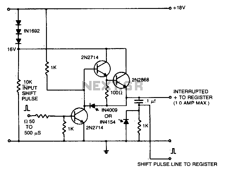
A 16V power supply can be synthesized using IN1692 rectifiers. A shift pulse input saturates the 2N2714, depriving the Darlington combination (2N2714 and 2N2868) of base drive. The negative pulse generated on the 15V line is differentiated to produce...
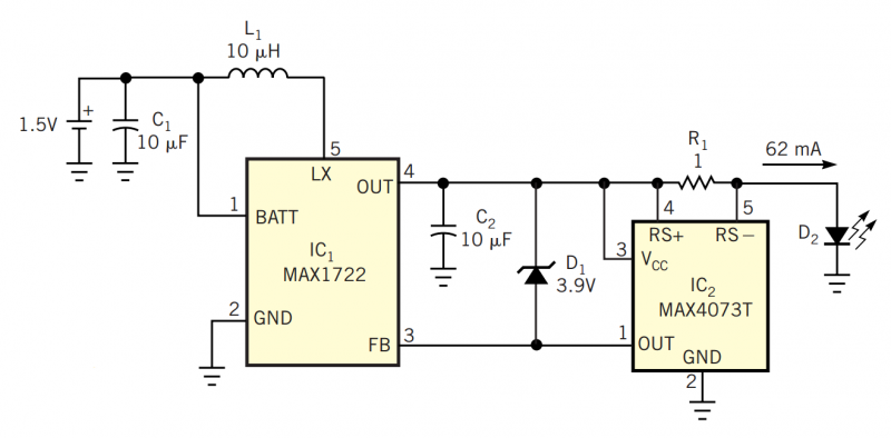
Although white LEDs are common in a variety of lighting applications, their 3 to 4V forward-voltage drop makes low-voltage applications challenging. Charge pumps and other ICs are available for driving white LEDs, but they generally don't work with the...

The servo motor is a type of traditional motor that serves as the execution component in automated devices. Its most significant characteristic is its controllability; when a control signal is applied, the servo motor rotates, with its speed being...
A servo is an error-sensing feedback control mechanism used to correct the performance of a system. A servo motor is a DC motor equipped with a servo mechanism. A servo motor is an electromechanical device that utilizes a closed-loop control...