
Servo Motor System Controller
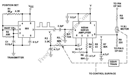
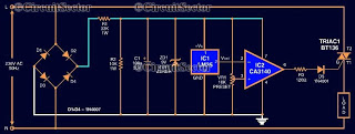
The servo system controller circuit operates by generating a pulse-width modulation (PWM) signal, which is essential for controlling the position of the servo motor. The 555 timer, configured in astable mode, produces a continuous square wave output. The frequency and duty cycle of this output can be adjusted by varying the values of the resistors and capacitors connected to the timer.
To implement this circuit, the following components are typically required: a 555 timer IC, two resistors, one variable resistor (potentiometer), one capacitor, and a diode. The resistors determine the frequency of the PWM signal, while the potentiometer allows for fine-tuning of the duty cycle, thereby controlling the angle of the servo motor. The capacitor smooths the output signal, ensuring stable operation.
The output from the 555 timer is fed into the control pin of the servo motor. The servo motor interprets the width of the PWM signal to adjust its position accordingly. By changing the duty cycle, the angle of the servo can be modified, allowing for precise control in various applications, such as robotics, automation systems, and remote-controlled devices.
This circuit is advantageous due to its simplicity, low cost, and the minimal number of additional components required, making it suitable for hobbyist projects and educational purposes in understanding basic servo control mechanisms.This is a Servo System Controller circuit. This circuit is used to control a servo motor remotely. This circuit uses the 555 and requires only six extra. 🔗 External reference
Related Circuits
This integrated circuit is highly efficient and does not require any external glue logic for operation. It features two pins to control a motor: one for direction and the other for stepping pulse triggers. The design is compact and...
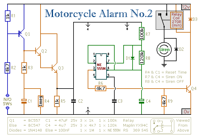
This circuit features an intermittent siren output and automatic reset. It can be operated manually using a key-switch or a hidden switch; but it can also be wired to set itself automatically when you turn-off the ignition. By adding...
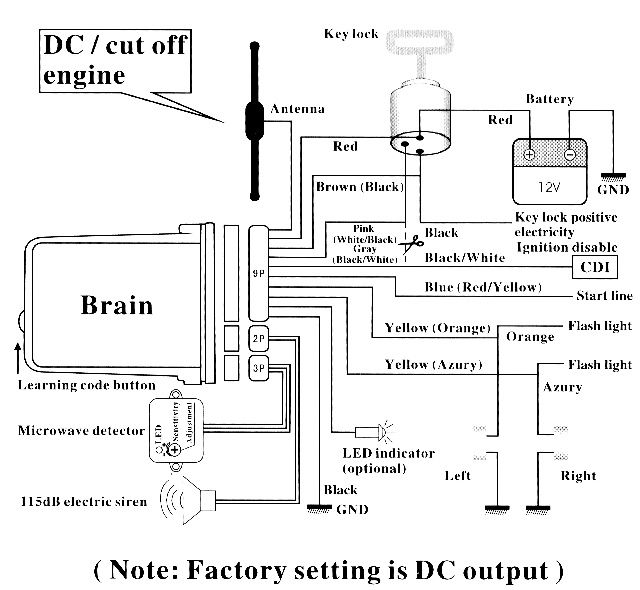
This document outlines the installation process for a SPY5000 two-way motorcycle alarm on a 1998 Honda CB250 Nighthawk motorcycle. The SPY5000 two-way motorcycle alarm system is designed to enhance the security of motorcycles by providing features such as remote...
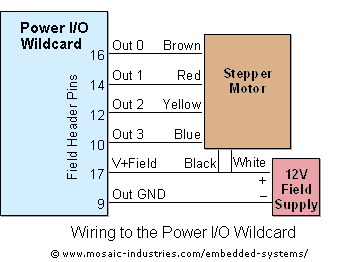
For optimal efficiency, set MAX_STEPPERS to the number of stepper motors being controlled, with a maximum limit of four. Motors are identified by indices 0, 1, 2, and 3. On the QCard, there is a trade-off between the number...
Computers often experience overheating due to prolonged use or high ambient temperatures, making temperature controllers essential. Accurate temperature measurement is necessary to ensure that the computer operates within a safe temperature range. A circuit diagram for a simple temperature...
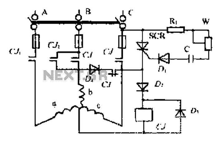
AC contactor controls suction units, with the motor activated simultaneously. A pair of contacts (CJ1) short-circuits the thyristor (SCR), turning it off. The contactor (C) is influenced by the diode's DC voltage. In the positive half-wave power cycle, the...