
shootable simon game
The circuit utilizes a 74HC14 hex inverting Schmitt trigger, which is configured to process the signal from the piezo hit sensor. The piezo sensor generates a voltage spike when it is struck, which is fed into one of the inputs of the 74HC14. Depending on the configuration, this can either trigger a high or low output, which is then routed to the Simon game’s switch input. The connection of the LED serves as a visual indicator of the circuit's operation, allowing for real-time feedback during testing.
The circuit design requires careful attention to the wiring and connections. Each piezo sensor should be securely mounted to ensure reliable operation, and the wiring must be insulated to prevent short circuits. Proper grounding practices must be followed, especially when using separate power supplies, to avoid potential damage to the components.
The overall assembly should be robust enough to withstand repeated impacts while maintaining functionality. The choice of materials, such as the plexiglass for the panel, should also consider impact resistance and weight to avoid any safety hazards. Testing the sensitivity of each piezo sensor prior to final assembly can help in selecting the most responsive units, ensuring consistent performance across all panels.
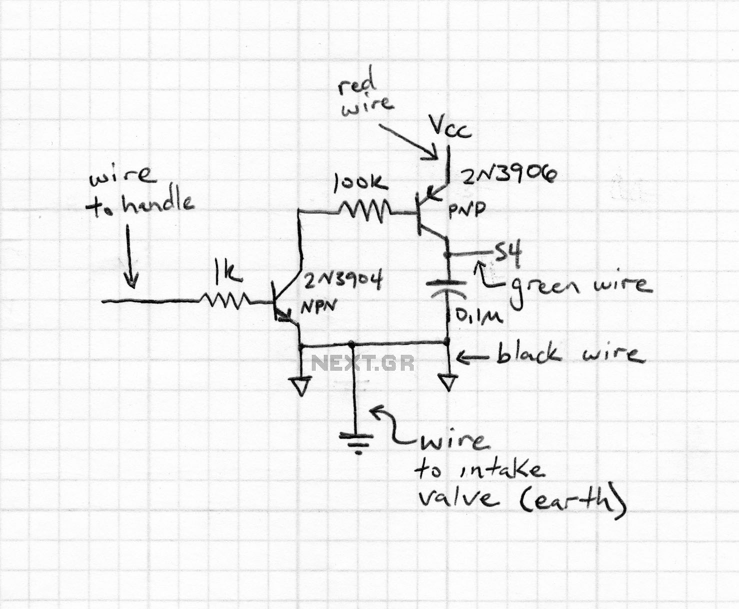
Safety precautions are crucial during both assembly and operation. Users should always wear appropriate eye protection to guard against any potential projectiles, especially when using this setup in a dynamic environment. The design's effectiveness can be further enhanced by experimenting with different configurations and placements of the piezo sensors to optimize their responsiveness to varying impacts.Here is the schematic for the circuit, including the connection to the piezo hit sensor. For testing, you can connect an LED between pins 3 and 4 of the 74HC14. Giving the plexiglass plate a good smack should either light or unlight the LED (depending on which way around you installed it). You`ll need 4 of these for a modification of a Simon game (1 per switch to actuate). In the case of the Spark Fun Simon game I used, the /HIT OUT would be connected to a switch input on the Simon PCB. I used the Simon game from Spark Fun, but you can use almost anything you want as long as you can trigger the buttons by applying a logical 0 or 1 to the right pin or contact.
In my Simon`s case, applying GND to the inner ring of the button contact does the trick. A logical 0 sent here will push the button. First, I de-soldered each LED under the button panel and extended them out on wires. I did this in order to have each LED shine on its matching plexiglass panel, instead of lighting the button. Next I soldered a wire from each button contact to each of the outputs of the piezo hit sensors. This is so that when the panel is shot, the LOW from the 74HC14 gets fed into the button input on the Simon game which triggers the input.
Therefore, shooting the panel is the same as pressing the button. I powered the piezo hit sensors from the +5V supply of the Simon game, but if you supply the hit sensors with a separate power source, remember to tie together the GND of both power supplies (that is, your piezo sensor`s power supply GND should be connected to the (-) of the battery connector on the Simon. ) Note: Only connect the GNDs! Do not connect the (+) of the two supplies! This is where mine got ugly. I drilled some holes in the plexiglass, tied them to a dowel, and hot-glued on the small sensor circuitboards.
Ugly, but functional. Here is the basic layout. Each plate got one of the LEDs as well, making sure to match up the right LEDs to the right inputs. Using it is straightforward of course, but make sure you only use it somewhere that flying and ricocheting Airsoft BBs will not be a problem. Angle the plexiglass plates so that the BBs ricochet off at a safe angle (for example, downwards into a box with a towel).
Always remember to wear eye protection. A video of a short demo is below I only make it to 3 shots before I screwed up. Not all piezo elements are created equal. Some were more sensitive than others a tap of my finger would trigger some while for others I had to smack a hefty screwdriver onto it to get a reaction. However, they all seemed to detect BB hits reliably. This was written by Administrator. Posted on Tuesday, January 16, 2007, at 3:14 pm. Filed under Projects. Bookmark the permalink. Follow comments here with the RSS feed. Both comments and trackbacks are currently closed. 🔗 External reference
Related Circuits

A miniature version of the classic PONG game was invented in 1966 by Ralph Baer. The game gained significant popularity in the 1970s. A later version featured a single 40-pin integrated circuit (IC). In 1973, the Dutch electronics magazine...
This circuit is designed to electronically simulate the tossing of a coin using a 4049 hex inverter integrated circuit (IC). It employs two of these ICs, specifically IC1a and IC1b, which are configured as an astable oscillator. This configuration...
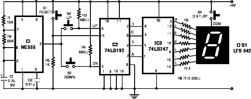
The following circuit illustrates the NE555 Timer used in an electronic scoring game circuit diagram. Features: The circuit consists of a timer integrated circuit (IC), along with various additional components. The NE555 timer is a versatile and widely used integrated...
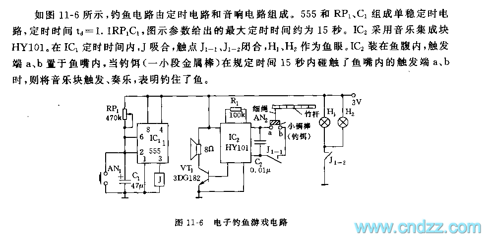
The fishing circuit, as illustrated in figure 11-6, comprises a timing circuit and an audio circuit. The components 555, RP1, and C1 form the single-shot circuit, with the defined time calculated as td = 1.1RP1C1. The maximum defined time...
This is a simple game circuit designed for multiplayer enjoyment. The objective is to score one hundred points within a limited timeframe. To restart the game, the S1 button switch must be pressed. It is important to ensure that...
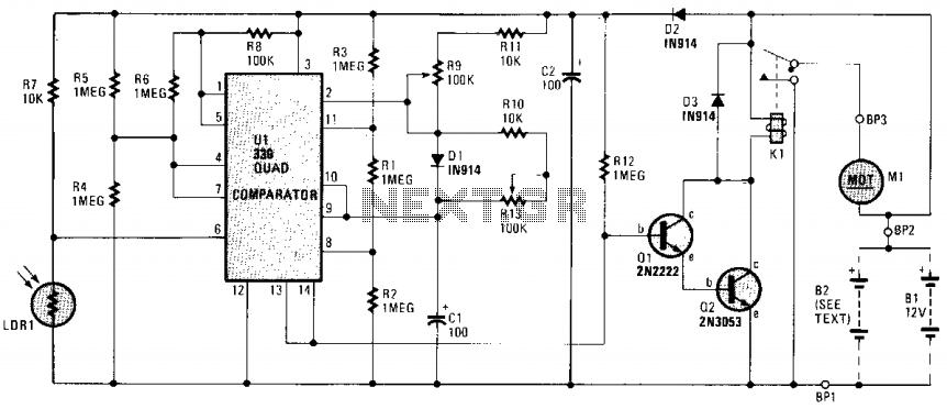
The circuit is constructed around an LM339 quad comparator (U1), which serves as the foundation for a Schmitt trigger, a timer circuit, and a window comparator. One comparator within the LM339 (pins 1, 7, 6), in conjunction with LDR1,...
Warning: include(partials/cookie-banner.php): Failed to open stream: Permission denied in /var/www/html/nextgr/view-circuit.php on line 713
Warning: include(): Failed opening 'partials/cookie-banner.php' for inclusion (include_path='.:/usr/share/php') in /var/www/html/nextgr/view-circuit.php on line 713