
Shortwave antenna amplifier

The wideband shortwave antenna amplifier is designed to enhance the reception of radio signals within the frequency range of 1 to 30 MHz. This amplifier is particularly useful for improving the performance of shortwave radio systems, which often require additional gain to effectively capture weak signals.
The amplifier's input stage is constructed using the MPF102, a popular JFET (Junction Field Effect Transistor) known for its low noise characteristics and high input impedance. This choice of transistor ensures that the amplifier does not significantly load the antenna, allowing for optimal signal reception. The MPF102 is configured to operate in the common-source mode, providing voltage gain and ensuring that the amplifier maintains a low noise figure.
The overall design of the amplifier includes additional stages that may consist of further amplification and filtering to refine the output signal. The gain of 15 dB indicates a moderate level of amplification, suitable for enhancing weak signals without introducing excessive distortion or noise.
Power supply considerations are crucial for the proper functioning of the amplifier. It typically operates on a low-voltage DC supply, which can be derived from batteries or regulated power sources. Bypass capacitors are often included in the design to filter out any power supply noise that could affect performance.
In summary, the wideband shortwave antenna amplifier is a critical component for enhancing the reception capabilities of shortwave radio systems, leveraging the MPF102 transistor to achieve a balanced combination of gain and noise performance across a broad frequency range. Proper implementation of this amplifier can significantly improve the listening experience for users of shortwave radio.This is a wide band shortwave SW antenna amplifier. The frequency band is 1 to 30 MHz and a medium gain of 15 dB. The input stage is built with MPF102 and.. 🔗 External reference
Related Circuits
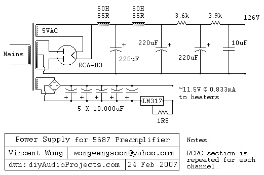
The RCA-83 rectifier utilizes 5VAC for the filament supply. The heaters for the 5687 tubes are powered by a full bridge rectifier consisting of MUR860 diodes, followed by five 10,000µF Elna capacitors. Current regulation is achieved through an LM317...
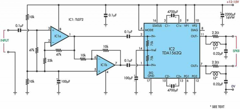
This circuit is based on a Philips class-H audio amplifier integrated circuit (IC) and can deliver 36W RMS or 70W music power, all from a 13.8V supply. The Mighty Midget Amplifier is capable of providing approximately 36W RMS continuous...
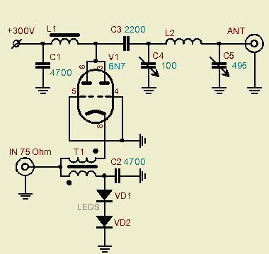
A powerful vacuum tube QRP amplifier designed for an 800mW QRPP homebrew telegraph vacuum tube transceiver named "3T." The decision to build this amplifier followed a period of using less than a watt of QRPP power for nearly a...
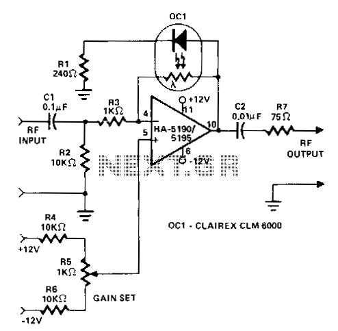
This circuit operates as a wideband adjustable automatic gain control (AGC) amplifier. It has an effective bandwidth of approximately 10 MHz and can handle RF input signal frequencies ranging from 3.2 to 10 MHz at levels between 40 mV...
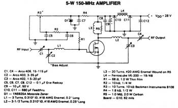
This is a 5W -150MHz RF amplifier circuit that utilizes the MRF123 TMOSFET. The MRF123 is a high-gain FET which may exhibit instability at both VHF and UHF frequencies; therefore, a 68 Ohm input loading resistor is employed to...
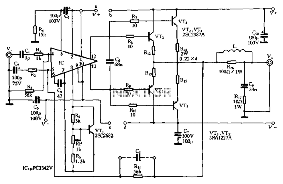
The pLPC1342V and NE are two companies involved in a tube amplifier circuit utilizing 2SA1227A and 2SC2987A transistors, achieving a maximum output power of up to 120W with a cutoff frequency of up to 500 MHz. The circuit, illustrated...