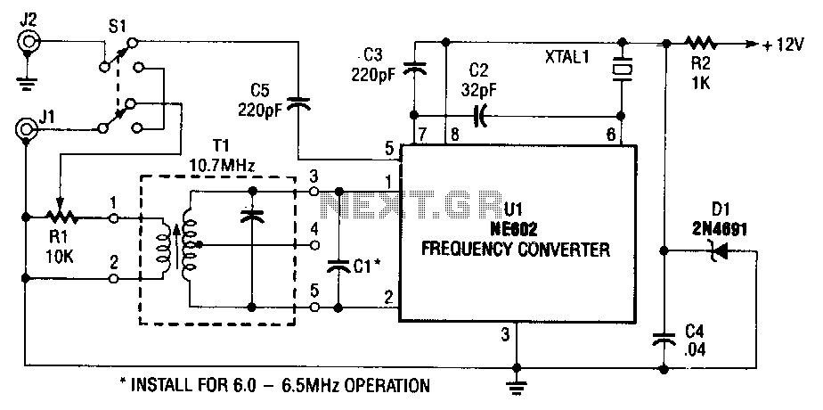
Shortwave-converter

The NE602 (U1) includes oscillator and mixer stages. The mixer merges the oscillator signal with the input RF signal to generate signals whose frequencies are the sum and difference of the input frequencies. For instance, a 7.5-MHz signal received by the antenna mixes with an 8.5-MHz oscillator frequency. The difference between these two signals is 1 MHz, which aligns with the center of the AM dial. Additionally, transformer T1 is a 10.7-MHz intermediate frequency (IF) transformer.
The NE602 integrated circuit is designed for applications requiring frequency mixing and signal processing. It operates as a double-balanced mixer, ensuring high linearity and minimal distortion. The oscillator stage within the NE602 can be configured to generate a stable local oscillator signal that is essential for effective mixing with the incoming RF signal.
In this specific application, the NE602 takes an incoming RF signal of 7.5 MHz from an antenna. This signal is then combined with a local oscillator frequency of 8.5 MHz. The mixing process results in two output frequencies: the sum (16 MHz) and the difference (1 MHz) of the two input frequencies. The generated 1 MHz signal is particularly significant, as it falls within the AM broadcasting band, allowing for effective demodulation of AM signals.
The transformer T1 plays a crucial role in the circuit by serving as a coupling device that matches the impedance of the mixer stage to the subsequent IF stage. With a specified frequency of 10.7 MHz, T1 is designed to enhance signal transfer and minimize losses, ensuring that the mixer operates efficiently. The choice of a 10.7 MHz IF is standard in AM radio applications, facilitating further processing and demodulation of the received audio signals.
Overall, this configuration emphasizes the importance of proper frequency mixing and signal processing in radio communications, utilizing the NE602 and transformer T1 to achieve desired operational characteristics in an AM receiver circuit.The NE602, U1, contains oscillator and mixer stages. The mixer combines the oscillator signal with the input rf signal to produce signals whose frequencies are the sum and difference of the input frequencies. For example, a 7.5-MHz signal is picked up by the antenna and mixes with the 8.5-MHz oscillator frequency.
The difference between those two signals is 1 MHz-right in the center of your AM dial. Transformer Tl is a 10. 7-MHz i-f transformer.