
Signal Chain Basics Audio metering enjoying the VU
The audio metering system described integrates several essential components to provide accurate monitoring of audio signals. The VU and PPM meters serve distinct purposes, with VU meters ideal for assessing loudness in traditional audio systems and PPM meters designed to prevent clipping in digital systems. The rectification process is crucial for accurate signal representation, especially for asymmetric signals, which necessitates the use of full-wave rectifiers and careful consideration of diode voltage drops. The choice of operational amplifiers is significant, as they must accommodate the specific voltage requirements of the system while maintaining high input impedance to avoid signal degradation. The peak-hold functionality enhances the monitoring system's ability to capture transient peaks, which is vital in both live and recorded audio environments. Overall, the design and implementation of audio metering circuits require a comprehensive understanding of audio standards, component behavior, and signal processing techniques to achieve high-quality audio monitoring.Audio metering is present in almost any equipment that plays or records audio from cell phones displaying bar graphs of audio output levels, to home stereos with flashing LEDS, to live broadcasting. There are multiple standards for audio metering that deal with the levels being monitored and time constants used for calculating the average.
The behavior of volume unit (VU) meters is defined in ANSI C16. 5-1942, British Standard BS 6840, and IEC 60268-17. These standards define 0 VU = +4d Bm, with an integration time of 300 ms. Traditionally, with a moving needle meter, this means that from zero signal to 0 VU, the needle should reach 0 VU within 300 ms (same for decay). This makes a traditional VU meter excellent for getting an idea of loudness, but a poor method for monitoring transients.
This was fine in traditional broadcast and recording systems, mainly based on tubes and tape, both of which tend to saturate elegantly. In today`s digital systems, clipping inputs or outputs sounds awful, so peak program meters (PPM) are used.
PPMs are similar to VUs, but, integration time is much faster (typically around 10 ms). Note that there are multiple standards bodies with definitions for the signal levels and exact integration times. Display technology is a big part of these standards. Getting the ballistics right to move a needle through 90 degrees (or more) with one percent of accuracy is much harder and slower than lighting a few LEDs!
Using LEDs, the quality of audio monitoring varies drastically. For example, a simple voice recorder product requires a different metering system from a mini-micro system using LEDs as a visual effect. In a live sound or broadcast environment accuracy is important, as well as seeing the difference between average loudness and the signal`s absolute peak.
Signal rectification is required mainly in comparator-style systems. Full signal rectification is required because not all signals are symmetric. The acoustic output of some musical instruments (and some voice) shows more pressure on the microphone in one direction. To monitor this accurately, the signal should be fully rectified. Be sure to compensate for the usual 0. 7 V diode drop. Figure 2 shows a full wave rectifier circuit. Such a circuit can be implemented in a very small space, using BAV99 dual diodes in a SOT23 packages, and 100 kOhm resistor networks.
For small voltage systems (3. 3V), a quad low-voltage rail-to-rail output operational amplifier (op amp) such as the LMV324 can be used in a single supply system, but ground should be replaced by Vcc/2. The dual output op amp used in this example is the LF353, because of its low cost, high impedance input, and wide voltage range support ( ±15V).
For systems that require monitoring peak versus direct signal (with its integration time), a peak-hold circuit (or code) can be used. In software this can be implemented by storing the ADC`s largest peak value in a separate register and holding it for a specific number of samples.
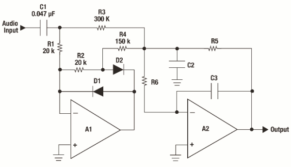
Whenever a new larger sample is received, simply overwrite the peak value and reset the counter. When the counter finally hits zero, reset the peak value to zero. In an analog circuit, the rectified output can be run through the circuit in Figure 4. D1 biases the output up a diode drop (~0. 7V), and is then dropped 0. 7V by D2. D2 ensures that audio content can only flow into C1 and R1, not back through the feedback circuit. The values of C1 and R1 set the decay time for the peak hold. The impedance of the comparator array ADC also acts as impedance to ground. Dafydd Roche is the Analog Professional Audio Marketing Manager at Texas Instruments. A graduate from the University of York (UK), Dafydd pours his passion and knowledge of audio and music making into his work, doing his part to help enable audio design engineers to make products that end users can`t wait to use. In between a hectic life of customer visits, 🔗 External reference
Related Circuits
The audio source will be a line-level audio signal ranging from -2V to +2V AC, which will be passed through a 220µF coupling capacitor followed by a two-pole low-pass filter (RC). The signal will be processed by an Analog-to-Digital...
The objective of this project was to design a compact portable mixer powered by a 9V PP3 battery, while ensuring high-quality performance. The mixer consists of three primary modules, which can be customized in quantity and arrangement to meet...
An audio equalizer circuit is utilized to modify the frequency response of an audio signal. This particular equalizer circuit is designed for adjusting the bass and treble (tone) levels of an audio amplifier. To integrate this equalizer circuit with...
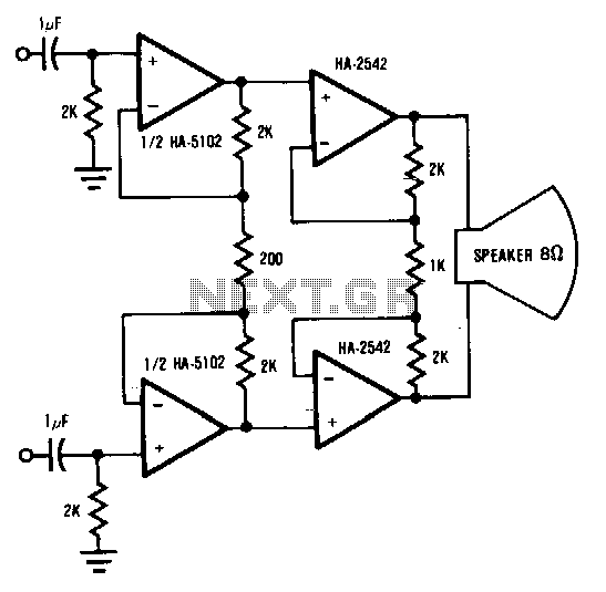
This circuit demonstrates a method to enhance the power capability of a drive system for audio speakers. Two HA-2542 amplifiers are utilized to operate on half cycles only, significantly increasing their power handling capacity. Bridging the speaker, as illustrated,...
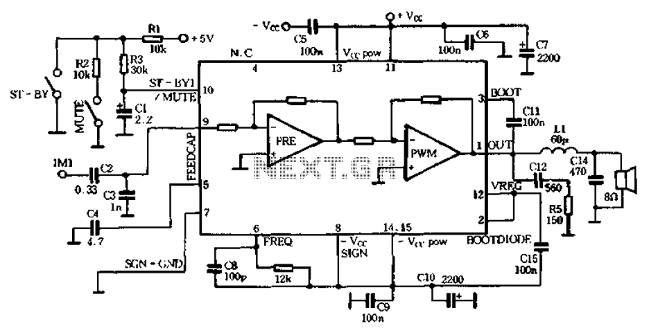
The PWM Class D audio amplifier has been the subject of exploration and reporting for over half a century. This technology is particularly attractive due to its high output efficiency, typically exceeding 85 to 90%. High output efficiency is...
Install the red LED at D2. Align the flat side of the LED with the PCB outline. Install a jumper wire at R4 and install a 220µF electrolytic capacitor at C8 with the negative side connected to ground. Connect...