
Silent Radio LED sign to Arduino
- Author: Bob Davis
- Date: April 25, 2011
- Version: 1.0
- Based on the work of Hari Wiguna
The schematic includes the pin assignments for row drivers and column shift registers. The setup function initializes the pins for output. The bitmap array represents the LED matrix, where each bit corresponds to an LED. The font data is defined for characters, with a space represented by the '@' character. Functions are provided to refresh the display and plot characters on the matrix.
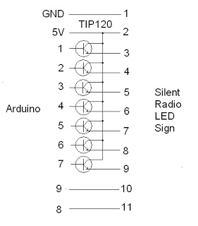
The schematic for the Silent Radio Driver illustrates a microcontroller-based LED matrix display system. The Arduino microcontroller is the central element, responsible for managing the display's operation. The row drivers are connected to pins 1 through 7, facilitating control over each row of LEDs. The column shift registers are connected to the clock and data pins (pins 8 and 9), enabling the microcontroller to send data to the display in a serial manner.
The bitmap array, defined as an 8x12 matrix, is utilized to represent the state of each LED in the display. Each element in the array corresponds to a row of the LED matrix, while the number of zones is calculated based on the size of the bitmap array. The font array contains the binary representation of characters, allowing for text to be displayed on the LED matrix.
The RefreshDisplay function is critical for updating the display, as it ensures that the display is turned off before any updates are made to prevent ghosting effects. The Plot function allows for individual LEDs to be turned on or off by manipulating the appropriate bits in the bitmap array.
This design emphasizes the importance of careful control of LED brightness and scrolling behavior, using software adjustments and hardware considerations to achieve the desired performance. The choice of current limiting resistors and the power supply voltage are critical for ensuring proper operation of the LED display while maintaining desired brightness levels.Working on the brightness problem, I know that the 4017 design did not work well because there was no way to turn off the sign while updating the shift registers. As a result I went back to having the Arduino directly drive the TIP120 drivers. Another possible solution might be to use an ULN2003`s as a level shifter. That would require a 6 or 7 vo lt power supply as well. I wanted to stay with a 5 volt power supply. I have observed that the Cadaces modules use 22 ohm current limiting resistors. The Silent Radio signs use 100 ohm resistors. Maybe changing the resistors is a better solution Here is the schematic. On the scrolling issue, I have suspects that the sign scrolls backwards because it is upside down. So I changed two lines of code so the sigh would work upside down and viola, it works. It now scrolls from right to left like it should have been doing. //*// // Name : Silent Radio Driver // // Author : Bob Davis // // Date : 25 April, 2011 // // Version : 1. 0 // // Based on work of Hari Wiguna - // //* // Pins for the row drivers int row1Pin = 1; int row2Pin = 2; int row3Pin = 3; int row4Pin = 4; int row5Pin = 5; int row6Pin = 6; int row7Pin = 7; // Pins for column shift registers int clockPin = 8; int dataPin = 9; // Set the pins to output to the circuit void setup() { pinMode(clockPin, OUTPUT); pinMode(dataPin, OUTPUT); pinMode(row1Pin, OUTPUT); pinMode(row2Pin, OUTPUT); pinMode(row3Pin, OUTPUT); pinMode(row4Pin, OUTPUT); pinMode(row5Pin, OUTPUT); pinMode(row6Pin, OUTPUT); pinMode(row7Pin, OUTPUT); } //= B I T M A P = //Bits in this array represents one LED of the matrix // 8 is # of rows, 7 is # of LED matrix we have byte bitmap[8][12]; // Change the 7 to however many matrices you want to use.
int numZones = sizeof(bitmap) / 8; // I will refer to each group of 8 columns (represented by one matrix) as a Zone. int maxZoneIndex = numZones-1; int numCols = numZones * 8; //= F O N T = // Font courtesy of aspro648 // // First char is @, next is A, B, etc.
Only lower case, no symbols. // The @ will display as space character. byte alphabets[][5] = { {0, 0, 0, 0, 0}, {31, 36, 68, 36, 31}, {127, 73, 73, 73, 54}, {62, 65, 65, 65, 34}, {127, 65, 65, 34, 28}, {127, 73, 73, 65, 65}, {127, 72, 72, 72, 64}, {62, 65, 65, 69, 38}, {127, 8, 8, 8, 127}, {0, 65, 127, 65, 0}, {2, 1, 1, 1, 126}, {127, 8, 20, 34, 65}, {127, 1, 1, 1, 1}, {127, 32, 16, 32, 127}, {127, 32, 16, 8, 127}, {62, 65, 65, 65, 62}, {127, 72, 72, 72, 48}, {62, 65, 69, 66, 61}, {127, 72, 76, 74, 49}, {50, 73, 73, 73, 38}, {64, 64, 127, 64, 64}, {126, 1, 1, 1, 126}, {124, 2, 1, 2, 124}, {126, 1, 6, 1, 126}, {99, 20, 8, 20, 99}, {96, 16, 15, 16, 96}, {67, 69, 73, 81, 97}, }; //= F U N C T I O N S = // This routine takes whatever we`ve setup in the bitmap array and display it on the matrix void RefreshDisplay() { for (int row = 0; row < 8; row+) { //- turn off the display - digitalWrite(row1Pin, LOW); digitalWnto the matrix - delayMicroseconds(500); } } // Converts row and colum to actual bitmap bit and turn it off/on void Plot(int col, int row, bool isOn) { int zone = col / 8; int colBitIndex = col % 8; byte colBit = 1 << colBitIndex; if (isOn) bitmap[row][zone] = bitmap[row][zone] | colBit; else bitmap[row][zone] = bitmap[row][zone] & (~colBit); } // Plot each character of the message one column at a time, updated the displ 🔗 External reference
Related Circuits
An exhaust fan is a crucial component in kitchens. This document presents a simple circuit designed to control kitchen fans by monitoring the ambient temperature. It is built around... The circuit for controlling an exhaust fan based on ambient temperature...
The crystal radio derives its name from the galena crystal (lead sulfide) utilized for rectifying signals. A "cat's whisker" wire contact was adjusted on the crystal's surface until a diode junction was established. The 1N34A germanium diode serves as...
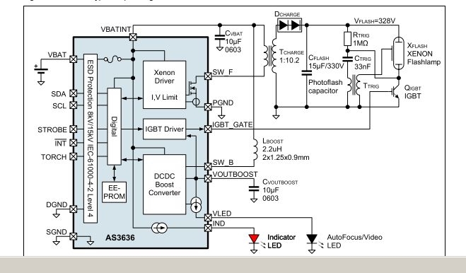
The AS3636 is a highly integrated photoflash charger that includes an IGBT driver, an inductive DC-DC boost autofocus/video LED driver, an indicator LED driver, and incorporates system-level ESD protection. The AS3636 is designed for efficient photoflash charging applications, providing a...
Here is another project that creates a scrolling LED display. This display consists of 64 LEDs arranged in a matrix configuration. The anodes are driven through a driver circuit. The scrolling LED display project utilizes a matrix of 64 LEDs,...
The advantage of LED technology is its longer lifespan compared to incandescent lamps, along with higher efficiency in the latest LED advancements. Additionally, LEDs are very compact; however, there are some limitations. LEDs, or Light Emitting Diodes, are semiconductor devices...

A simple FM transmitter circuit can be designed using the MC2833 integrated circuit, which is intended for cordless telephones and FM communication equipment. It features a microphone amplifier, a voltage-controlled oscillator, and two auxiliary transistors. The final output frequency...