
Simple 100W inverter schematic design
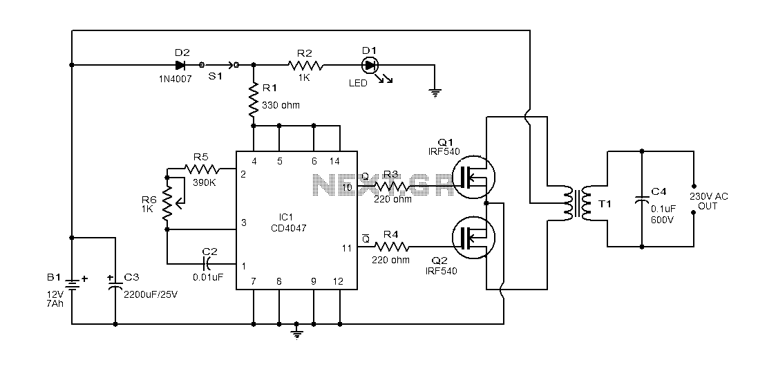
The inverter circuit operates by utilizing the CD4047 IC, which serves as the heart of the system, generating square wave signals necessary for driving the MOSFETs. The astable mode of the CD4047 is configured to produce a continuous square wave output, which is essential for the switching operation of the MOSFETs Q1 and Q2. The output frequency can be adjusted by selecting appropriate resistor and capacitor values connected to the CD4047.
The IRF540 MOSFETs are chosen for their ability to handle high currents and voltages, making them suitable for this inverter application. Proper heat sinking is crucial to prevent thermal damage during operation, as the MOSFETs will dissipate heat when switching high currents.
The transformer used in this circuit is a critical component, as it steps up the voltage to the desired output level. A transformer rated for 230V and 150VA is recommended to handle the power requirements efficiently. The primary and secondary windings must be correctly configured to ensure proper operation and safety.
Safety precautions should be observed while assembling and testing the circuit. The use of a lead-acid battery provides a reliable power source, but care must be taken to avoid over-discharging the battery, which can lead to reduced lifespan. The circuit is designed for low-power applications and is suitable for educational purposes or small-scale projects.Explanation Here is a simple 100-watt using IC CD4047 and IRF540 MOSFET of the inverter circuit diagram. The circuit is simple, low cost, or even assemble a veroboard. CD 4047 is a low-power CMOS astable/monostable multivibrator IC. Here, it is connected to the production of two pulse sequences 10 11 0.01S 180 degree phase IC pins and as a non-multivibrator. Pin 10 is connected to the gates of Q1 and pin 11 is connected to the gate of Q2. Resistors R3 and R4 prevent loading of each MOSFET IC. When the first 10 feet were accounted for output AC voltage current to flow through the upper half of the positive half of the transformer primary high in the first quarter.
When the second quarter by 11 feet high current flows in the opposite direction through the lower half of the transformer primary, account negative half its output AC voltage. Schematic Precautions B1 can be a 12V/6AH lead-acid batteries. Q1 and Q2 must install the appropriate heat sink. 9-0-V T1 may be a primary, secondary, 230V 150VA transformer. Do not expect from this circuit. It is very simple for low-grade applications.
Related Circuits
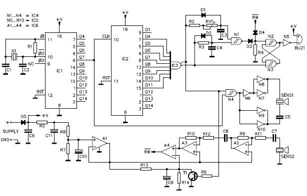
A simple ultrasonic parking sonar electronic project can be designed using this schematic circuit. This ultrasonic parking sonar project features an adjustable detection range from 5 cm to 1.5 meters and a detection angle of 5 degrees. The circuit...
Motor control, energy efficiency of inverter (AC drive) selection, and parameters setting guidance in the mining industry: vector control, open loop or closed loop control, with energy braking unit or energy feedback unit. In the context of motor control for...
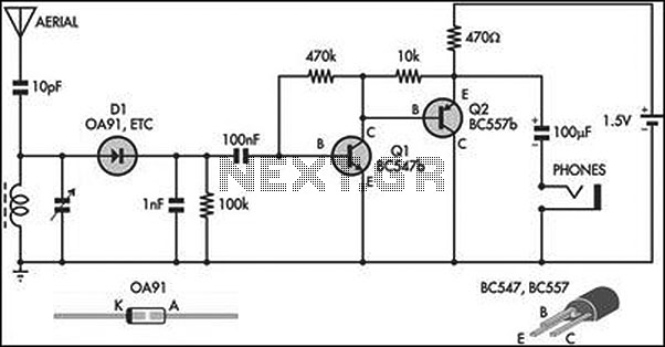
This circuit is an amplified crystal set. The inductor can be a standard AM radio ferrite rod antenna, while the tuning capacitor is a variable plastic dielectric gang designed for small AM radios. The aerial tuned circuit feeds diode...
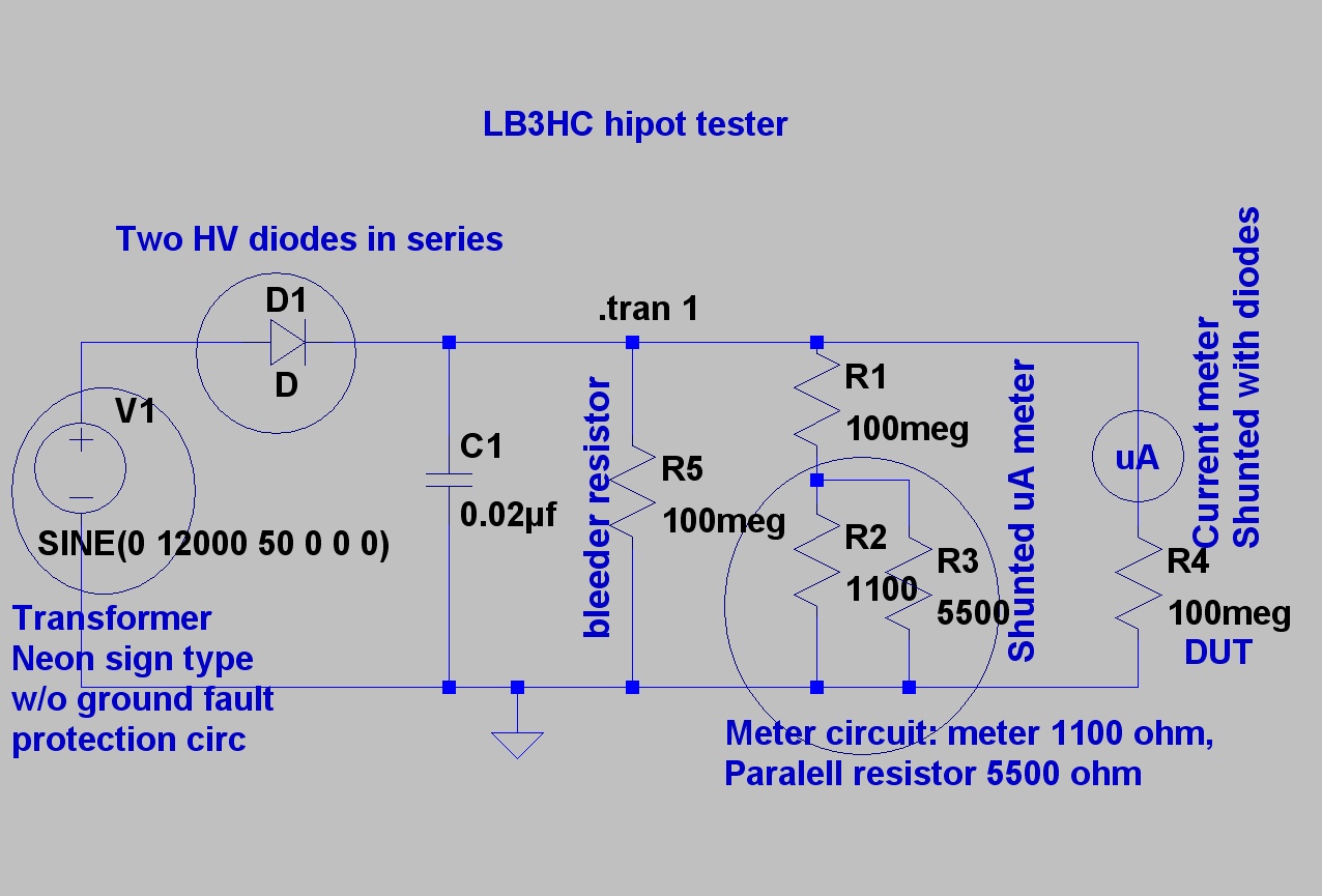
The design is based on concepts from K8CU and AG6K, but the circuit has been simplified and uses different components. The mechanical encapsulation has also been modified. LTspice was utilized to verify the tester prior to construction. The schematic...
Switching regulator subsystems are designed for use as DC to DC converters. The 3V to 40V DC converter circuit utilizes switching regulators, which are increasingly favored over linear regulators due to the demand for higher conversion efficiency in modern...

In typical push-pull driver applications, the NPN-PNP transistor pair is alternately activated and deactivated using a square-wave signal. A basic driver circuit employs an inverter between the V1 and V2 inputs to toggle the output transistors. However, mismatched turn-on...