
Simple ADS-B Receiver
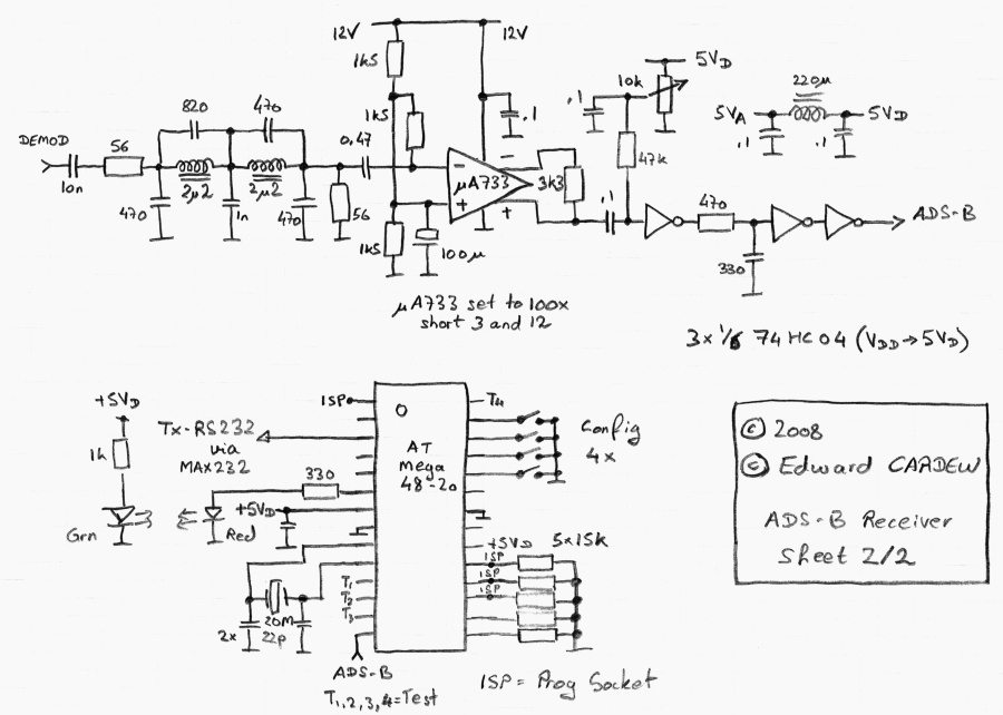
The project is centered around repurposing existing analog satellite receiver tuners, which involves specific modifications to optimize performance for desired signal processing applications. The Automatic Frequency Control (AFC) is disabled to ensure a stable frequency lock, while the Automatic Gain Control (AGC) is set to maximum gain to enhance signal reception. The output of the project is a 480 MHz Intermediate Frequency (IF) signal, crucial for further processing.
The choice of IF converter is flexible, allowing the use of either a satellite receiver with a 70 MHz IF output or a TV receiver/converter that has been tuned to accept a 1090 MHz input. The configuration of extracting the IF signal after the Surface Acoustic Wave (SAW) filter is essential for filtering out unwanted frequencies and ensuring clean signal processing. The TV converter is noted for its excellent performance, while the satellite receiver option requires additional filtering to reduce the IF bandwidth to around 5 or 6 MHz, which is critical for minimizing noise and improving signal clarity.
The antenna system consists of a "Spider" antenna optimized for 1090 MHz operation, which is known for its compact design and effective radiation pattern. The inclusion of a high-quality satellite line amplifier enhances the signal strength before it travels through approximately 30 meters of coaxial cable to the receiver. The receiver, a modified FUBA unit, operates with a local oscillator set to 1126 MHz, with the Phase-Locked Loop (PLL) disabled to accommodate the specific frequency requirements of this application.
Signal amplification is achieved using two BF494 transistors; the first serves to amplify the IF signal, while the second acts as a buffer to ensure signal integrity before demodulation. The demodulation process converts the IF signal into a baseband signal, which can then be processed for further applications. The performance of the demodulated signal is adjustable via the biasing of a BAT43 diode, allowing for fine-tuning of the signal quality to meet specific project requirements. This comprehensive setup exemplifies a practical approach to utilizing existing technology for innovative signal processing applications.The new project uses old analog satellite receiver tuners that have to be modified so that the AFC is disabled and the AGC usually set to maximum gain. The output is the 480MHz IF signal. The IF converter can be for example a Satellite receiver with 70 MHz IF output or a TV receiver / converter tweaked to 1090 MHz input and the IF taken after the
SAW. The TV converter solution gives excellent results and the satellite receiver at 70 MHz works just as well but need a handmade filter to filter the IF down to about 5 or 6 MHz bandwidth. A simple "Spider" antenna for 1090 MHz with a good Satellite line amplifier like the xxx is housed in a watertight container.
About 30 meters of cable link this antenna to the reciever. The receiver is a FUBA xxx modified to run with an Lo of 1126 MHz and the PLL disabled as it does not work at this frequency. The input signal is again amplified by a xxx amplifier. The first BF494 amplifies the IF and the second BF494 buffers the signal which is then am demodulated.
The quality of the demodulated signal can be adjusted by offsetting the bias of the BAT43 diode. 🔗 External reference
Related Circuits
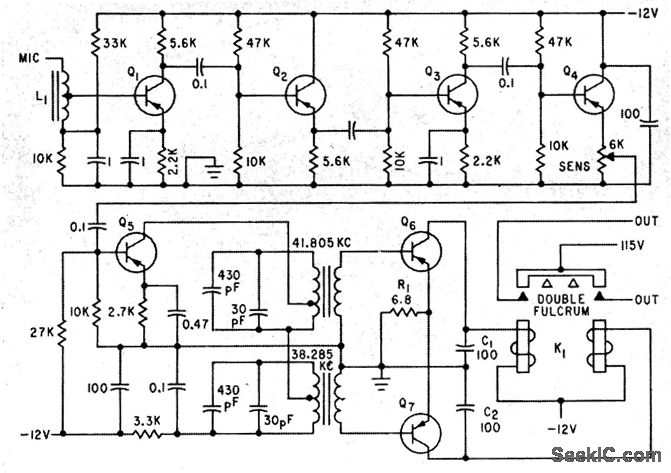
A five-stage amplifier consisting of transistors Q1 through Q5 amplifies the control signals at frequencies of 38.285 kHz and 41.805 kHz. Transistors Q6 and Q7 function as class B detector-amplifiers, thereby eliminating the need for separate diode detectors. The...
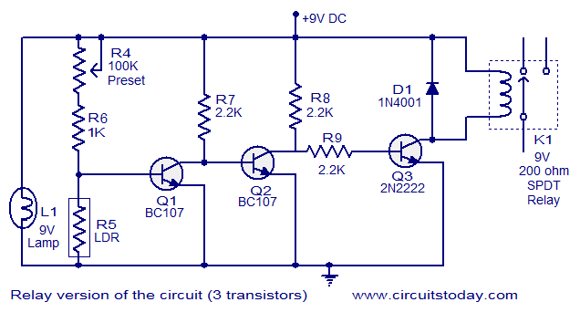
This document describes a simple fire alarm circuit utilizing a Light Dependent Resistor (LDR) and lamp combination for fire detection. The alarm activates by detecting smoke generated during a fire. When smoke is present, the circuit triggers an audible...
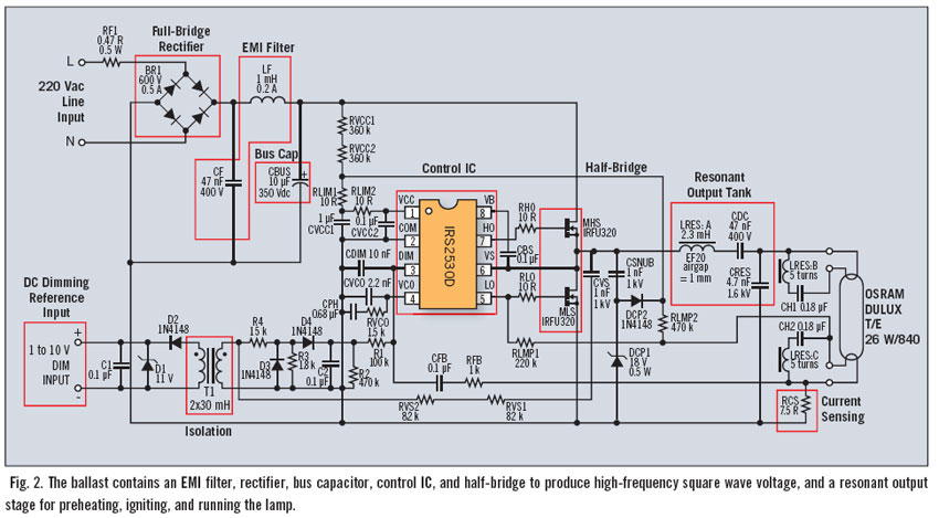
Fluorescent dimming systems can enhance visual comfort and lower utility costs through strategies such as daylight harvesting, demand reduction, and scheduled dimming. A dimming electronic ballast plays a crucial role in this system. To execute dimming functions, the ballast...
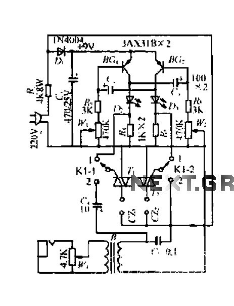
A 220V mains power supply is reduced using a control circuit designed by N. Guanidine D. Yi. The circuit features a spike Bode and provides a +9V voltage supply. It includes components such as a control port (G), a...
These circuits provide overvoltage protection in the event of a voltage regulator failure or the application of an external voltage. They are intended for use with a power supply that incorporates some form of short circuit protection, such as...
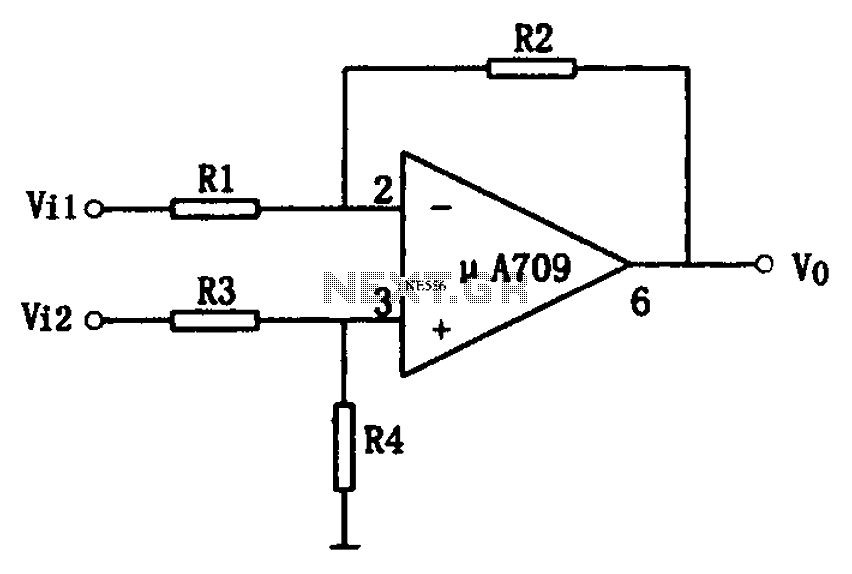
The simple differential amplifier circuit consists of two input signals, Vi1 and Vi2, which are connected through resistors R1, R3, and R4, forming a voltage divider circuit at the op-amp input. Vi1 is applied to the inverting input of...
Warning: include(partials/cookie-banner.php): Failed to open stream: Permission denied in /var/www/html/nextgr/view-circuit.php on line 713
Warning: include(): Failed opening 'partials/cookie-banner.php' for inclusion (include_path='.:/usr/share/php') in /var/www/html/nextgr/view-circuit.php on line 713