
Simple AM Transmitter
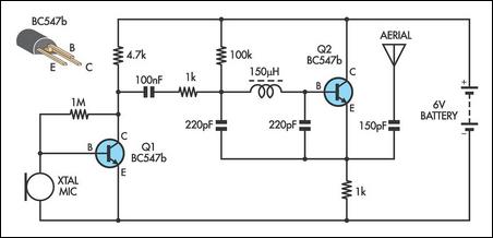
This AM transmitter circuit is designed for ease of assembly and compactness. The choice of a single-winding inductor simplifies the construction process, eliminating the complexity associated with tapped inductors. The RF choke utilized serves not only as an inductor but also ensures that the circuit operates efficiently within the radio frequency range. The fixed capacitors are chosen to streamline the design, reducing the number of components and the overall size of the circuit board.
Tuning the transmitter to a desired frequency is facilitated by the adjustable capacitance method. By altering the values of the fixed capacitors, the operating frequency can be finely tuned. This design choice allows for flexibility in tuning while maintaining a compact form factor. The high input impedance provided by the biasing resistor allows for the effective use of low-cost audio input devices, such as crystal earpieces, making this circuit accessible for hobbyists and educational purposes alike.
The circuit may include additional components such as a power supply, which should be carefully selected to match the voltage and current requirements of the transistor. Proper grounding and shielding techniques should also be employed to minimize interference and enhance the performance of the transmitter. Overall, this AM transmitter design represents a practical solution for those interested in radio transmission and electronics experimentation.There are not many AM transmitters that are easier to build than this one because the inductor is not tapped and has a single winding. There is no need to wind the inductor as it is a readily available RF choke (eg, Jaycar Cat LF-1536).
To make the circuit as small as possible, the conventional tuning capacitor has been dispensed with and fixed 22 0pF capacitors used instead. To tune it to a particular frequency, reduce one or both of the 220pF capacitors to raise the frequency or add capacitance in parallel to lower the frequency. Q1 is biased with a 1MO resistor to give a high input impedance and this allows the use of a crystal ear piece as a low cost microphone.
🔗 External reference
Related Circuits

You have 4 transistors, wired as ON OFF switches. Two signal lines allow you to run the motor in one direction, when reversed, the motor runs in the other direction. It's very straightforward to use and build, but be...

The servo motor is a type of traditional motor that serves as the execution component in automated devices. Its most significant characteristic is its controllability; when a control signal is applied, the servo motor rotates, with its speed being...
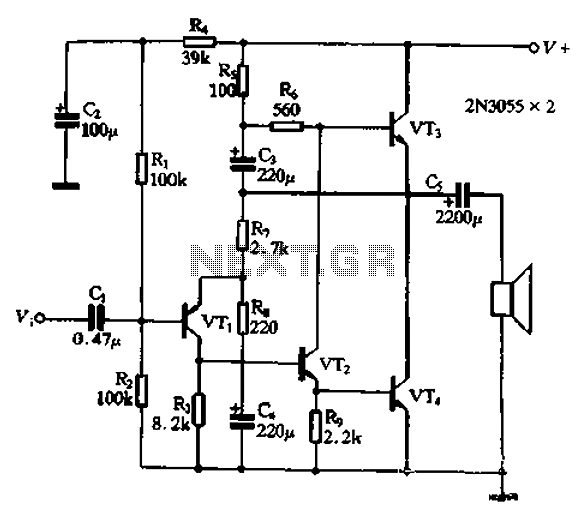
The circuit illustrated in Figure 240 is straightforward, utilizing only four transistors to process the input voltage, resulting in a large, inverted output. This configuration serves as a high-performance amplifier, delivering excellent high-fidelity power discharge capabilities. The input stage...
This circuit is a simple air flow detector that signals the presence of air flow. The sensor utilized is a filament incandescent lamp. Components include an air flow detector, a sensor, an LED, and an LM339 operational amplifier. The air...
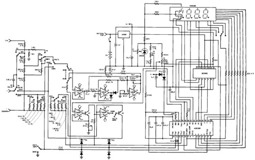
The following circuit illustrates the design of a simple digital multimeter circuit diagram. This circuit employs the ADD3501. Features include the combination of voltage measurements, among others. The circuit design for a simple digital multimeter utilizing the ADD3501 integrates several...
This is a TMP01 Temperature Sensor Transmitter circuit. This circuit is used in industrial environments to transmit the signal differentially on a wire pair. The TMP01 Temperature Sensor Transmitter circuit is designed to provide accurate temperature measurements in industrial settings,...
Warning: include(partials/cookie-banner.php): Failed to open stream: Permission denied in /var/www/html/nextgr/view-circuit.php on line 713
Warning: include(): Failed opening 'partials/cookie-banner.php' for inclusion (include_path='.:/usr/share/php') in /var/www/html/nextgr/view-circuit.php on line 713