
simple audio amplifier
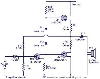
The described circuit begins with a preamplifier stage that employs the 2N2222 transistor (Q1). This transistor serves as the input stage, amplifying weak signals before they are processed further. The configuration of Q1 allows for significant gain, which is crucial for improving the signal strength.
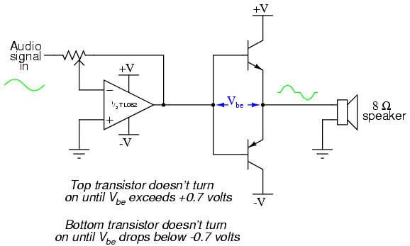
Transistor Q3 (2N3053) plays a critical role in this circuit as it is connected to the base of Q2 (2N2905A). This arrangement forms a complementary symmetry output stage, which is essential for driving the load effectively. The complementary pair configuration enhances the efficiency of the circuit by allowing for push-pull operation, where one transistor conducts during one half of the signal cycle while the other conducts during the opposite half. This results in improved linearity and reduced distortion in the output signal.
The output of the preamplifier can be obtained from the junction of the emitters of Q2 and Q3. This point serves as the amplified output, providing a stronger signal that can be fed into subsequent stages of the circuit, such as additional amplification or processing stages. The careful selection of transistors and their arrangement ensures optimal performance of the preamplifier, making it suitable for a variety of applications in audio and signal processing systems.The first part of the circuit here is a preamplifier consisting of transistor Q1(2N2222). The collector of the Q3 is coupled to the base of Q2 (2N2905A), which forms a complementary symmetry pair with Q3 (2N3053). The amplified signal is available at the junction of emitter of two transistors. 🔗 External reference
Related Circuits
More: A comprehensive electronic schematic is required to illustrate the functionality and interconnections of various components within a circuit. The schematic should clearly depict the arrangement of components such as resistors, capacitors, diodes, transistors, and integrated circuits, along with...
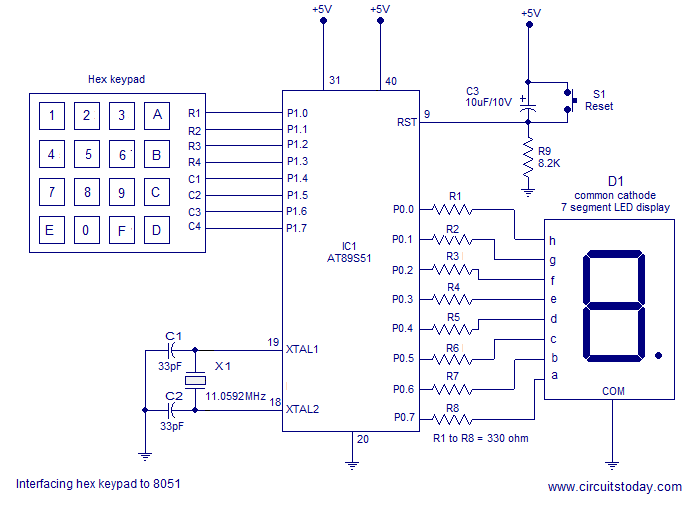
Interfacing a hex keypad to an 8051 microcontroller. The AT89S51 is utilized in this setup. A circuit diagram and assembly language program are included. A testing video is also provided. The interfacing of a hex keypad with the AT89S51 microcontroller...
The microphone has high sensitivity in the audio range, but in the ultrasonic range, the sensitivity decreases rapidly. The receiver is very sensitive. To prevent overdriving and feedback due to the high sensitivity of the microphone in the audio...
This document describes a simple 2.4 GHz SWR meter that utilizes surplus microwave hardware. The main component is a MECA -20/-20 dB Directional Coupler, which operates within a frequency range of approximately 700 MHz to 2.5 GHz. This directional...
This is a simple oscillator with multiple resistors in series. When you press any switch, the circuit starts oscillating. You can use variable resistors instead of the 1k resistors. Using variable resistors, you will be able to tune the...
The closer the two transistors are matched, the better the performance. It is advisable to use TIP41 and TIP42 transistors, which are closely matched NPN and PNP power transistors with a dissipation rating of 65 watts each. If a...