
Simple Capacitive Touch Sensor
Capacitive touch sensors leverage the inherent capacitance created by human contact to facilitate user interaction with electronic devices. The operational principle hinges on detecting variations in capacitance induced by the presence of a finger, which significantly alters the electrical characteristics of the sensor circuit. The design outlined employs a square-wave generator, specifically utilizing a CD4093 Schmitt trigger, to produce a stable 300 kHz signal. This frequency is crucial for maintaining sensitivity to changes in capacitance.
The RC network, consisting of resistors and capacitors, plays a vital role in shaping the response of the circuit. The inclusion of a fly-back diode protects against voltage spikes, ensuring the integrity of the circuit components. The isolation capacitor (470 pF) further enhances the stability of the measurements by isolating the sensor from noise and interference.
The conversion of pulse width changes into a voltage signal is a critical step, allowing the circuit to translate physical touch into an electrical signal that can be processed. The LM339 comparator is employed to compare this voltage against a predetermined reference voltage, which is adjustable based on the capacitance characteristics of the contact plate. The output from the comparator can trigger subsequent electronic actions, such as activating a relay or interfacing with microcontrollers.
The design considerations also emphasize safety, particularly when integrating capacitive touch sensors into devices that may be connected to mains power. The requirement for a Class Y capacitor ensures compliance with electrical safety standards, protecting users from potential electric shock hazards.
Overall, this capacitive touch sensor design exemplifies an effective approach to human-device interaction, balancing sensitivity, reliability, and safety within electronic systems.Capacitive touch sensors are based on the electrical capacitance of the human body. When, for example, a finger comes close to the sensor, it creates a capacitance to Earth with a value of 30 to 100 pF. This effect can be used for proximity detection and touch-controlled switching. Capacitive switches have clear advantages compared to other types of touch switches (for example 50 Hz or 60 Hz detection or resistance detection), but are often more complex to implement. Manufacturers such as Microchip have in the past designed specialist ICs for this purpose. However, it is still possible to design a reliable capacitive detector and/or switch using only a limited number of standard components.
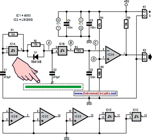
In this design we detect the change in the pulsewidth of the signal when the contact is touched. In Figure 1 the following stages can be recognised, from left to right:- a square-wave generator with a frequency of 300 kHz, using a Schmitt trigger IC (CD4093); - an RC network with a fly-back diode, followed by a Schmitt trigger/contact plate with an isolation capacitor of 470 pF; - an RC network that converts the change in pulsewidth into a voltage. This voltage is about 2. 9-3. 2 V when the plate is touched (and 2. 6 V when it isn`t touched); - an LM339 comparator is used to compare the voltage at point C with a reference voltage (D).
The latter is set to about 2. 8 V using a potential divider. As long as the contact plate is touched the output of the circuit will be active. To make the operation of the circuit clearer we have shown the signals at various points in Figure 2. The dotted line represents the signal when the plate is touched, the solid line when it isn`t touched.
The reference voltage at D has to be set up once via potential divider R4/R5 (change the value of R4). The required value is strongly dependent on the surface area of the contact plate (this is usually a few square centimeters).
Larger surfaces increase the capacitance and the voltage at C will therefore be greater when the plate isn`t touched. The reference voltage at D should then be set closer to 3. 4 V. The touch sensor can therefore also be made to work with larger areas (such as the complete metal enclosure of a device).
The circuit only works when a connection for higher frequencies (300 kHz) is made to Earth in some way. The circuit therefore doesn`t work in battery-powered systems without a connection to Earth. In many systems without a direct connection to Earth there is sufficient parasitic capacitance to the mains Earth.
In some cases it will be necessary to add an extra capacitor between the mains Earth and the Ground of the circuit. To comply with safety regulations this capacitor should be rated for>3-4 kV (i. e. a Class Y capacitor). The output signal can be used in various ways to switch on systems. The addition of an extra Schmitt trigger to the output is recommended in many cases, especially if the output connects to a digital input.
🔗 External reference
Related Circuits
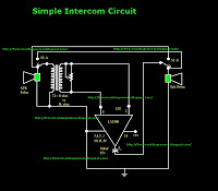
This is a simple intercom circuit utilizing the common IC LM380. In this configuration, the switch is set to the talk position for the speaker on the left, while the other participant is in the listening position. If the...
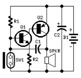
The system involves positioning a small magnet near the stalk switch SW1, which is connected to the hand or garments of the individual carrying the bag via a tiny cable. Due to the compact nature of the circuit, it...
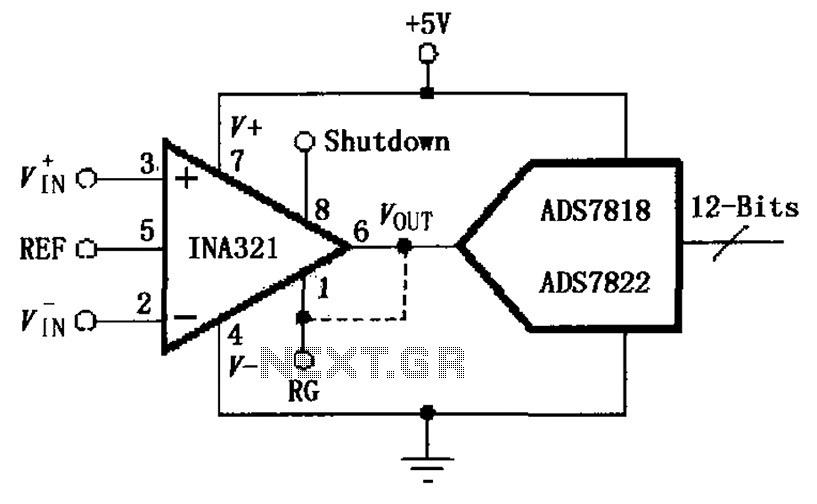
The INA321/322 is configured to directly drive the capacitive input of an A/D converter. Due to its low output resistance, the INA321/322 can effectively handle high frequency signals and directly drive capacitive loads. The input voltage is amplified by...
Introduction The design of off-line constant voltage, constant current (CVCC) power supplies using the NCP1014 for devices such as cell phones, hand tools, and similar battery chargers can present various challenges when low cost and circuit simplicity are required...
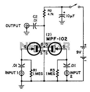
Here is an interesting mixer circuit. With it, signals from audio to high-frequency RF can be effectively combined. Additionally, this circuit provides some gain with a low noise figure. The inputs can accommodate nearly any level or impedance, and...
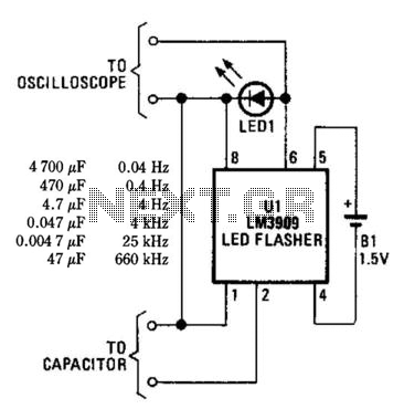
An LM3909 LED flasher functions as an oscillator, with the frequency determined by the capacitor connected to its terminals. The LED can be utilized to visually count frequency using a stopwatch for large capacitors (C > 500µF). The LM3909 is...