
Simple Car Preamplifier and Artificial Earth
The preamplifier circuit described operates with a standard configuration, ensuring that the input signal is AC coupled. This design choice is essential for blocking any DC components that may be present in the input signal, thereby preventing potential distortion or saturation of the amplifier stage. The use of capacitors for AC coupling is a common practice in audio and signal processing applications.
The circuit employs an artificial ground, established by two resistors, R1 and R2. This configuration effectively creates a virtual ground at half the supply voltage, which is typically around 13.8V in automotive applications. This voltage level is optimal for interfacing with a 12V battery system, ensuring compatibility with the vehicle's electrical architecture. By setting the artificial earth at this midpoint voltage, the circuit can maintain proper signal integrity and allow for symmetrical signal handling.
Gain control is facilitated through the adjustment of resistors R105 and R205. By selecting lower resistance values, such as 4.7kΩ, the maximum gain of the preamp can be limited to 3 (equivalent to 10dB). This level of gain is often sufficient for various audio applications, providing a good balance between signal amplification and noise performance. It is important to note that excessive gain can lead to distortion, particularly in environments with significant electrical noise, thus careful consideration of these resistor values is advisable to optimize performance based on the specific application requirements.
Overall, this preamp circuit exemplifies a straightforward yet effective design, suitable for a range of automotive and audio applications, ensuring reliable performance while maintaining simplicity in its configuration.The preamp circuit is completely conventional, and by necessity is AC coupled throughout. The artificial earth is derived by two resistors (R1 and R2), which will set the "earth" at exactly 1/2 the supply voltage. This is nominally 13.8V in all cars, since this is the proper charging voltage for a 12V battery. To reduce the maximum gain, simply reduce the values of R105 and R205. For example, reducing these to 4k7 will provide a maximum gain of 3 (10dB), which in reality is probably enough.
🔗 External reference
Related Circuits
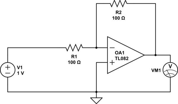
Considering a simple circuit as illustrated below, when the voltage source activates suddenly (changing from 0V to 1V), current will flow through the resistor R1. Assuming an ideal operational amplifier (op-amp) that draws no current, and an ideal voltmeter...
More: A comprehensive electronic schematic is required to illustrate the functionality and interconnections of various components within a circuit. The schematic should clearly depict the arrangement of components such as resistors, capacitors, diodes, transistors, and integrated circuits, along with...
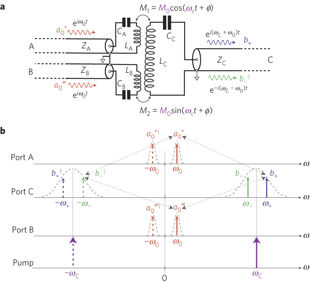
The circuit schematic of the UDC consists solely of dispersive components. Two low-frequency series LC resonators, with equal inductances (LA=LB) and capacitances (CA=CB), are connected to two input semi-infinite transmission lines, designated as A and B. These resonators are...
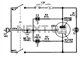
The circuit is straightforward and reliable when connected properly. Under standard operating conditions, only lamps 1 and 3 should illuminate. If lamp 2 activates, it indicates that the cold lead is at 117 volts above ground. The described circuit operates...
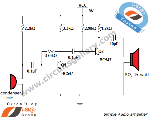
The output of the condenser microphone is coupled through a 0.1 µF coupling capacitor, which serves to eliminate DC components from the audio signal. Transistor Q1 is configured in a collector-to-base biasing mode, achieved with a 470kΩ resistor. This...
A unit that is often very useful for isolating two stages in sound circuits. This circuit includes an amplification unit with a gain of X1. Total negative feedback is not employed; instead, only local feedback is used, resulting in...
Warning: include(partials/cookie-banner.php): Failed to open stream: Permission denied in /var/www/html/nextgr/view-circuit.php on line 713
Warning: include(): Failed opening 'partials/cookie-banner.php' for inclusion (include_path='.:/usr/share/php') in /var/www/html/nextgr/view-circuit.php on line 713