
Simple CB transmitter with BD329
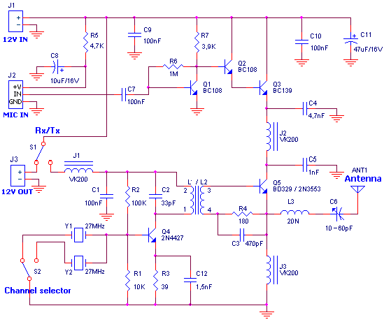
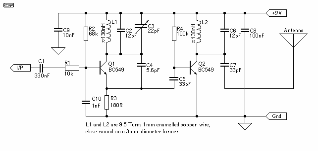
The circuit described is a basic AM transmitter that operates at a frequency of approximately 27 MHz. The essential components include a power supply, voltmeter, inductor, variable capacitor, and a microphone. The transmitter is powered by a +12V DC supply, with a current consumption expected to be between 0.7A to 1A, which indicates the power requirements for the operation of the circuit.
The inductor, labeled as L1/L2, is adjustable and plays a crucial role in tuning the transmitter to the desired frequency. The core of the inductor can be adjusted using a screwdriver, which changes the inductance and thus affects the frequency of emission. The variable capacitor, denoted as C6, is also adjustable and works in conjunction with the inductor to fine-tune the frequency. The goal is to achieve the highest possible amplitude modulation (AM) signal, which is indicated by the output observed on the voltmeter.
A 50W load is connected in place of the aerial, which is critical for proper signal transmission. The voltmeter is connected at the output to monitor the voltage levels, ensuring the transmitter operates within the desired parameters. During operation, when the microphone is connected and audio input is provided, the user should observe an increase in the reading on the multimeter, indicating successful modulation of the audio signal onto the carrier wave.
The expected output power of the transmitter is approximately 2.5W, which is suitable for short-range communication applications. If the setup is correct, the modulation depth should increase by approximately 30-35% when speaking into the microphone, demonstrating effective transmission of audio signals. This circuit can be used in various applications, including hobbyist projects, educational demonstrations, and basic communication systems.For the regulation it needs a voltmeter (with needle better) and charge 50W/5W. Connect charge 50W in the place of aerial, with the voltmeter in the exit voltmeter. Be supplied the transmitter with + 12V. It will be supposed we have consumption between 0,7-1A. With a screwdriver we regulate the core of inductor L1/L2 and later the variable C6 until we see the biggest tendency. We connect the microphone and speaking we observe the clue in the multimeter. If all have become right will be supposed the tendency, speaking, to go up roughly 30-35%. Tendency of catering: + 12V/1A DC. Frequency of emission at AM: ~27MHz. Force of expense: 2,5W 🔗 External reference
Related Circuits
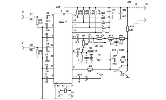
This is the BH1417 USB FM Transmitter, which features a built-in Phase-Locked Loop (PLL) circuit. It converts low-frequency audio signals into high-frequency signals, allowing any audio device equipped with an FM radio (such as stereo systems, car CD players,...
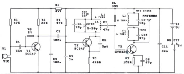
The modification presented involves using a 2N2219 NPN transistor to replace T2 and a 2N3553 NPN transistor to replace T3. Both transistors are categorized as VHF transistors. It is necessary to attach a heatsink to the last transistor. No...
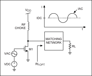
This application note provides a concise overview of power amplifier theory and presents simulation results that offer insights into the operation of the power amplifier across all of MAXIM's LFRF transmitters and transceivers. Power amplifiers are critical components in communication...
The circuit of the transmitter is shown in Figure 1, and as you can see it is quite simple. The first stage is the oscillator, and is tuned with the variable capacitor. Select an unused frequency, and carefully adjust...
This is a simple Arduino project for a soil moisture sensor that will light up an LED at a certain moisture level. It uses the Arduino Duemilanove microcontroller. This project employs a soil moisture sensor to monitor the moisture content...
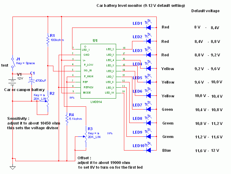
This circuit utilizes the widely available LM3914 integrated circuit (IC). The IC is straightforward to operate, does not require external voltage regulators due to its built-in voltage regulation feature, and can be powered from nearly any voltage source. The LM3914...
Warning: include(partials/cookie-banner.php): Failed to open stream: Permission denied in /var/www/html/nextgr/view-circuit.php on line 713
Warning: include(): Failed opening 'partials/cookie-banner.php' for inclusion (include_path='.:/usr/share/php') in /var/www/html/nextgr/view-circuit.php on line 713