
simple digital counter by

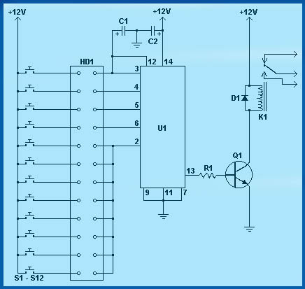
The circuit design integrates essential digital components, including flip-flops and counters, to facilitate event counting and frequency measurement. The use of a 4029 BCD counter IC allows for efficient binary-coded decimal output, which is crucial for applications requiring numerical display. The seven-segment display provides a user-friendly interface for visualizing the decimal output, enhancing usability.
The configuration of the DIP switch enables users to set specific values, which are then processed by the counter. The incorporation of a clock pulse generator, realized through a NAND gate oscillator, ensures that the counter operates continuously at a defined frequency until manually interrupted. This feature is particularly useful for applications requiring real-time counting.
Capacitors are strategically placed throughout the circuit to stabilize power supply voltages and filter out noise, which is critical for maintaining the integrity of digital signals. The 0.1 µF ceramic capacitors serve to decouple the power supply from transient spikes, thereby enhancing the reliability of the circuit during operation.
Overall, this design exemplifies a practical approach to digital counting applications, showcasing the integration of fundamental electronic components with an emphasis on stability and user interaction.The basic digital circuits are Flip Flop and Counter, both are here. This circuit can be cascaded to make even a 6 digit event counter, even a simple frequency counter can be made. These are best done with microcontrollers today. Then what if you have to design your own microcontroller on a FPGA, so the basics have to be sound, hence you have to k
now what gates, flip flops and counters are. a. Set the DIP Switch as you like and then Press the Set button. The BCD value will be at the 4029 output, The Decimal value will be seen in the seven segment Display. Now try for different dip switch settings and see the BCD and Decimal output. c. Now Click the Clk - clock or count button, the switch will latch, press it again to release. If you toggle it once the counter will get a single pulse and it will count it, see the BCD and decimal displays.
Now you turn it on and leave it, the counter will keep counting one per second till you turn it off, the clock nand gate is wired to be an oscillator. Add 104 CD, 0. 1uF ceramic disc cap to all the ICs across the supply pins. Also add a 104 CD cap across Inc switch and one across the Set switch for power on default settings 🔗 External reference
Related Circuits
The growth in the number of LCD segments increases the pin count required for the LCD driver package. An LCD driver IC with a key-scan function alleviates the workload on the microprocessor. However, this increase in pin count complicates...
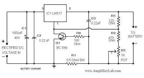
The circuit diagram of a lead-acid battery charger is presented here. The main component of this circuit is the IC LM317. The lead-acid battery charger circuit utilizing the LM317 voltage regulator is designed to efficiently charge lead-acid batteries while providing...
A digital storage oscilloscope (DSO) is a very important piece of test equipment that can do the jobs that a normal CRO just can't handle. Such as capturing single shot and widely spaced waveshapes, and looking at non-repetitive signals...
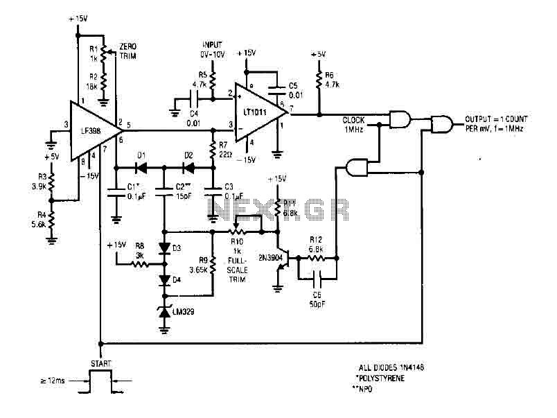
The simple 4-digit converter circuit has an output count of 1, designed for a frequency range from f-IMHz to 10.000 MHz. All diodes used in the circuit are IN4146 "POLYSTYRENE" NPO. The circuit utilizes the LF398 at the input...
Circuit diagram schematics of electronic keys, electronic locks, digital electronic locks, transistor code locks, and combination electronic locks. The circuit schematics for electronic locking mechanisms encompass a variety of designs tailored to enhance security and convenience in access control systems....
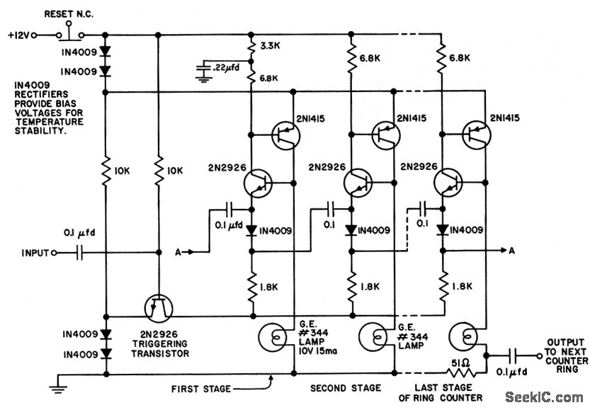
The circuit utilizes only six components per stage. By integrating counter and indicator functions, it achieves low battery consumption. Once the reset button is released, a 0.22 µF capacitor ensures that the first stage activates. Current is drawn by...
Warning: include(partials/cookie-banner.php): Failed to open stream: Permission denied in /var/www/html/nextgr/view-circuit.php on line 713
Warning: include(): Failed opening 'partials/cookie-banner.php' for inclusion (include_path='.:/usr/share/php') in /var/www/html/nextgr/view-circuit.php on line 713