
Simple Electromagnetic Field Detector Schematic

This circuit operates as an electromagnetic field detector, leveraging a radial inductor as a sensitive probe to capture low-frequency electromagnetic radiation. The design is straightforward, with a focus on utilizing readily available components. The inductor, with a value of 1mH, serves as the main sensing element, converting changes in magnetic fields into electrical signals. The choice of op-amp, particularly the LF351, enhances the circuit's performance by minimizing noise, which is crucial when detecting low-level signals.
The gain control provided by the 2.2M potentiometer allows for fine-tuning of the output signal, enabling the user to adjust the sensitivity based on the environmental conditions or the specific application. The output is designed to interface with headphones, making the circuit user-friendly for real-time audio feedback. The inclusion of a 3.5mm stereo plug facilitates easy connection and disconnection of the probe, enhancing the circuit's versatility.
The circuit's ability to detect hidden wiring, even when buried under plaster, showcases its practical applications in various fields, including electrical maintenance, safety inspections, and even hobbyist electronics projects. The effective range of detection for transformer hum and the interference from domestic appliances demonstrates its utility in identifying electromagnetic fields in everyday environments.
Future enhancements, such as the implementation of a meter output, would provide a visual representation of the detected fields, further increasing the circuit's functionality and ease of use. Overall, this circuit serves as a valuable tool for those interested in exploring the electromagnetic fields present in their surroundings.This circuit is sensitive to low frequency electromagnetic radiation and will detect for example hidden wiring or the field that encompasses a transformer. Pickup is by a radial type inductor, used as a probe which responds well to low frequency changing magnetic and electric fields.
Ordinary headphones are used to for detection. The field that su rrounds a transformer is heard as a 50 or 60Hz buzz. The circuit is below:- I threaded a length of screened cable through an old pen tube and soldered the ends to a radial type can inductor. I used 1mH. The inductor fitted snugly into the pen tube. The opposite end of the cable connects to the input of the op-amp. Any op-amp should work here, possibly better results may be achieved with a low noise FET type such as the LF351.
The 2M2 potentiometer acts as a gain control and the output is a pair of headphones. Stereo types can be used if they are wired as mono. I used an 8 ohm type, but the circuit should work equally well with higher impedance types. The probe (shown below) may be connected via screened cable and a 3. 5mm stereo plug and socket. The sensitivity of this circuit is good. Mains wiring buried an inch in plaster can be detected with precision. A small load on the electric supply is all that is needed; a 20 watt desk lamp or similar will suffice. The hum field surrounding a transformer can be detected oat over 7 inches. Domestic appliances such as videos and alarm clocks all produce interference which can be heard with the probe.
The electric field surrounding a loudspeaker or earpiece can also be heard. Try lifting a telephone and place the probe near the earpiece. A telephone pickup coil can be used in place of the inductor if desired. I will make an improved version of this circuit with a meter output later. link 🔗 External reference
Related Circuits
A graphical representation of a system. It often refers to electronic circuits on a printed circuit board or in an integrated circuit (chip). See logic gate and HDL. A graphical representation of a system serves as a crucial tool in...
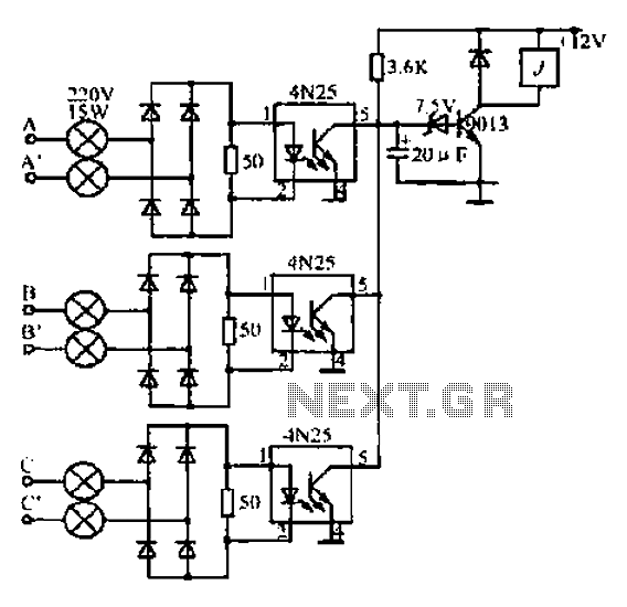
A, B, and C are used for a large power split-phase system. The A + BC range generator phase line features an A-A indole path string containing two 220V/15W bulbs. The bulbs recover based on macro instructions from J...
Connect the two sections of the variable capacitor (C3) in series to linearize the tuning somewhat. Use the connections on either end of C3 and do not use the middle lead. The gain is sufficient to drive an earphone....
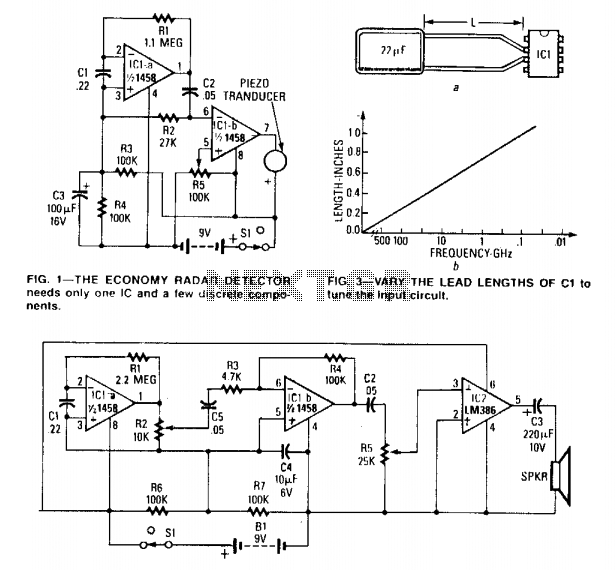
The circuit can be tuned to respond to signals between 50 MHz and 500 GHz. The economy model is illustrated in Figure 1, while the deluxe model is depicted in Figure 2. The first operational amplifier (op-amp) in each...
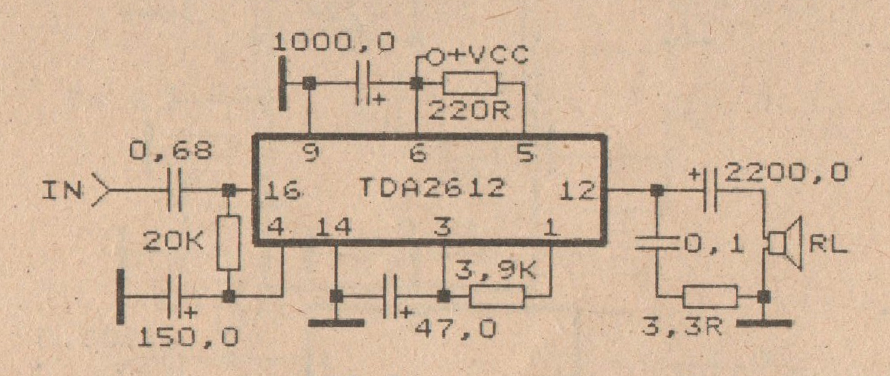
This amplifier circuit is based on the IC TDA2612 produced by Siemens. The minimum voltage required for this circuit is 10 volts, while the maximum voltage is 35 volts DC. The power output is 25 watts with a 4-ohm...
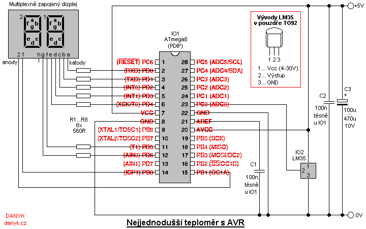
This is a simple digital thermometer utilizing an Atmel AVR microprocessor, capable of measuring temperatures in the range of 2 to 99 °C with a resolution of 1 °C. The circuit is managed by an Atmel AVR ATmega8, ATmega8L,...