
simple emergency led light circuit
The emergency LED light circuit is designed to operate under conditions where the main power supply is disrupted. The circuit begins with a 220V AC input, which is transformed down to 12V DC using a suitable transformer and rectifier configuration. This 12V output is then fed into an LM317 voltage regulator, which is configured to output a stable 7.37V. The LM317 requires two resistors for voltage setting: a fixed 240-ohm resistor and a variable resistor (typically 1.2K ohms) to fine-tune the output voltage.
When the main power supply is available, the LED indicator remains off, and the battery is charged. The circuit ensures that the transistor Q1 remains in the off state during this charging phase, preventing any current from flowing to the LED array. The LED indicator serves a dual purpose: it illuminates when the battery is charging and confirms that Q1 is not conducting.
Upon detection of a voltage drop, such as during a brownout, the transistor Q1 is activated, allowing current to flow to the 16 white LEDs connected in parallel. Each LED draws approximately 20 mA, resulting in a total current draw of about 320 mA when all LEDs are illuminated. The circuit is designed to utilize a 6V, 4.5Ah rechargeable battery, which can sustain the LED operation for up to 14 hours when fully charged.
This emergency LED light circuit is effective for providing illumination during power outages, ensuring safety and visibility. The simplicity of the design and the availability of components make it an excellent project for both novice and experienced electronics enthusiasts.This emergency LED light is simple, inexpensive and easy to build. The circuit to the battery and when the main source is not available, such as brownouts, white LEDs turns on automatically. Initially, the output voltage from 220V to 12V converter is fed to the input of LM317 regulator. Then, this voltage is regulated to 7. 37V with 240 ohms and th e combination of the resistance of 1. 2K (see LM317 Calculator). At this time, the battery is in charging mode and the transistor Q1 is off. LED serves two purposes, one is mainly to give us an idea of the battery is charging and the other is to ensure that Q1 is off. During voltage drops, the transistor Q1 is on and supplies the current to 16 white LED of about 20 mA each, so a fully charged battery (6V/4.
5Ah) may last up to 14 hours. 🔗 External reference
Related Circuits
In this circuit, two 567 tone decoders are utilized. One functions as an oscillator, while the other acts as a detector. Connecting TP1 and TP2 allows U2 to receive the signal from U1, resulting in pin 8 of U2...
Several RS232 transceiver circuits are used for communication between microcontrollers and other devices, such as PCs or RS232 devices. This document presents a collection of well-known RS232 transceiver circuits. The circuit utilizes the MAX232 from Maxim's devices, which is...
This circuit utilizes a standard loudspeaker, enabling it to function as a microphone. It allows for the use of an inexpensive loudspeaker in this capacity. Sound waves impacting the speaker cone result in variations in the voice coil. The...
This is a light dimmer circuit. It does not include any special features and is a typical TRIAC-based dimmer circuit. This circuit is designed to operate with... A TRIAC-based light dimmer circuit is a common electronic design used to control...
This circuit is permanently plugged into a mains socket and NI-CD batteries are trickle-charged. When a power outage occurs, the lamp automatically illuminates. Instead of illuminating a lamp, an alarm sounder can be chosen. When power supply is restored,...
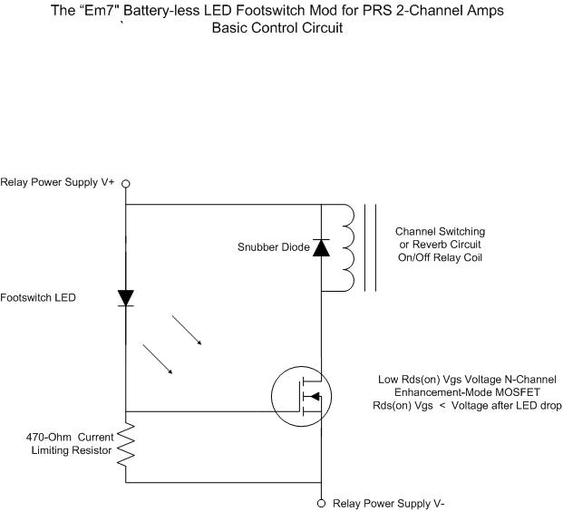
For individuals seeking LED-based footswitching without the inconvenience of battery installation, a battery-less LED-based footswitch modification is being developed for 2-channel amplifiers. This solution is designed to work with the existing TRS jack and footswitch, and it will involve...
Warning: include(partials/cookie-banner.php): Failed to open stream: Permission denied in /var/www/html/nextgr/view-circuit.php on line 713
Warning: include(): Failed opening 'partials/cookie-banner.php' for inclusion (include_path='.:/usr/share/php') in /var/www/html/nextgr/view-circuit.php on line 713