
Simple FM Transmitter Circuit
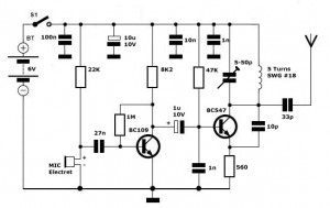
The simple FM transmitter circuit utilizes a transistor to modulate audio signals onto a radio frequency carrier wave. The circuit typically consists of a few key components: a transistor, resistors, capacitors, and an inductor. The transistor acts as the main amplifying element, allowing the circuit to generate the necessary RF signal for transmission.
In operation, an audio input signal, such as from a microphone or audio player, is fed into the base of the transistor. The transistor modulates this audio signal onto a carrier frequency, which is determined by the values of the inductor and capacitor in the circuit. The output from the collector of the transistor is then coupled to an antenna, which radiates the modulated signal into the surrounding environment.
To achieve a transmission distance of approximately 300 meters, the circuit may require an appropriate power supply, typically a battery or DC power source, and the antenna must be designed to match the frequency of operation for optimal performance. The choice of components, particularly the transistor type and the values of the passive components, will significantly influence the efficiency and range of the transmitter.
Tuning the circuit can be accomplished by adjusting the variable capacitor or inductor, allowing the user to select the desired frequency for transmission. Proper shielding and layout considerations are essential to minimize interference and ensure compliance with local regulations regarding unlicensed transmission. This simple FM transmitter circuit serves as an excellent introduction to radio frequency design and modulation techniques.Simple FM Transmitter Circuit This simple FM transmitter circuit was built using a transistor with a transmission distance of about 300m around your home. It`s.
Related Circuits
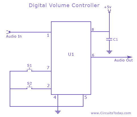 Volume Control Circuit Schematic using DS 1669 Potentiometer IC
A digital volume control circuit diagram using DS 1669, a potentiometer IC.This can be used as a digital volume controller for audio amplifiers and other applications..
 led metronome circuit
The LED Metronome is a modern interpretation of a classic device which is a staple of music teachers, students and composers everywhere. This circuit uses 12 LEDs to simulate the sweeping motion of the pendulum and a speaker with a simple amplifier to generate a tick as the LEDs at...

 Simple-tesla-coil
The Tesla coil described here can.generate 25,000 V. So, even though the output current is low, be very careful! The main component is a flyback transformer from a discarded TV. A new primary windin_g is needed. Begin by winding 5 turns of #18 wire on the core. Then,...