
Simple Fuse Monitor Indicators
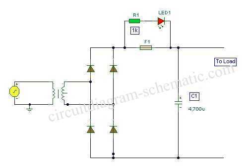
The fuse monitor circuit is designed to provide a straightforward method for detecting fuse failures within an electrical system. The circuit operates using minimal components, which enhances reliability and reduces the likelihood of component failure. The primary components involved in this circuit are an LED (LED1) and a current-limiting resistor (R1).
When the fuse (F1) is intact, the circuit remains in a normal operating state, and the LED remains off, indicating that the electrical path is complete and functioning correctly. However, if the fuse blows due to an overload or short circuit, the circuit configuration changes. The blown fuse creates a short circuit condition, allowing current to flow through the LED. As a result, LED1 illuminates, providing a clear visual indication that the fuse has failed and requires replacement.
The resistor (R1) plays a crucial role in this circuit by limiting the current flowing through the LED when it is illuminated. This current-limiting feature is essential to prevent damage to the LED due to excessive current. The value of R1 must be chosen carefully to ensure that it allows sufficient current to illuminate the LED while remaining within the safe operating limits of both the LED and the power supply.
This circuit can be implemented in various applications where fuse monitoring is critical, such as in power distribution panels, automotive systems, and consumer electronics. Its simplicity and effectiveness make it an ideal solution for providing immediate feedback on the status of fuses, enhancing safety and maintenance efficiency.This is a circuit diagram fuse monitor circuit indicators. This very simple circuit uses only two components, but only with a single resistor and LED this circuit provides visual indication when the fuse has blown. LED1 is usually dead, a short circuit by the fuse, F1. Please note that the LED will only illumininatet in damaged condition, ie with a short circuit or shunt the load.
In this case the current is reduced to a safe level by R1 🔗 External reference
Related Circuits
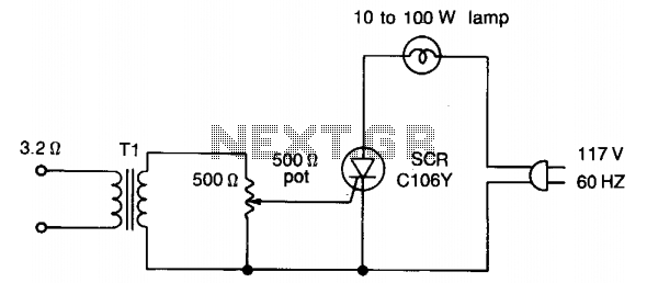
Transformer Tl can be any matching transistor type in the range of 500/500 to 2500/2500 ohms. No connections from the SCR or its components are connected to ground. For safety, maintain the 117-V line voltage from the amplifier connections;...

This audio peak detector enables the monitoring of a pair of stereo channels using a single LED. The circuitry employed for both the left and right channels is identical. The audio peak detector circuit is designed to provide a visual...
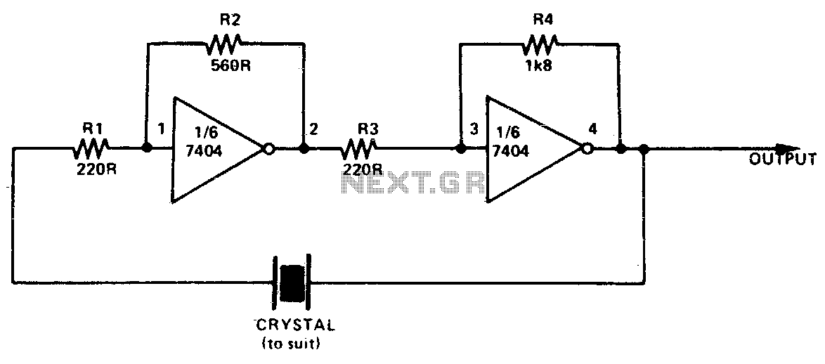
This simple and inexpensive crystal oscillator consists of one-third of a 7404 IC, four resistors, and a crystal. The inverters are biased into their linear regions by resistors R1 to R4, while the crystal provides the necessary feedback. Oscillation...

This is a simple 555 timer circuit suitable for oscillating applications. To slow down the strobe effect, replace the 220 µF capacitors with 1000 µF capacitors. For a faster strobe effect, use a 150 µF capacitor. Additionally, R1 can...
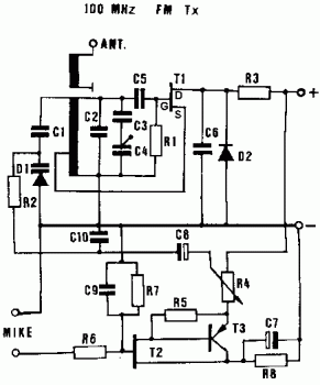
The frequency range is 100-108 MHz. The circuit is a mono circuit that accepts audio input from either a microphone or another source. The input impedance is 1 MΩ, with an input sensitivity of 5 mV and a maximum...

LM339-based peak detector circuit. Simple and easy to construct. Operates from a 5V DC single supply. LM339 is a dual comparator. The LM339-based peak detector circuit is designed to capture and hold the peak value of an input signal. This...