
Simple-high-voltage-supply
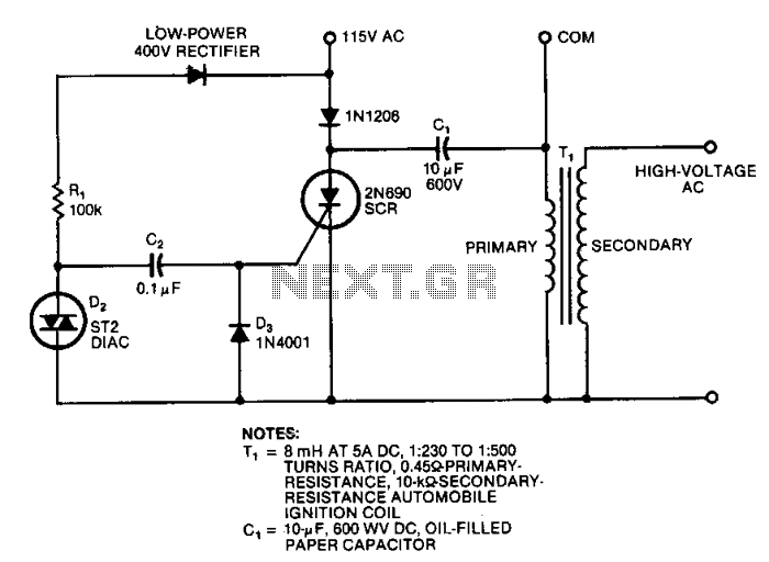
This circuit generates high-voltage pulses using an inexpensive auto ignition coil. By adding a rectifier to the output, the circuit produces high-voltage direct current (DC). The input to the circuit is 115 Vac. During the positive half cycle of the input, energy is stored in capacitor C1, which is charged through diode D1 and the primary winding of transformer T1 (the coil). During this period, the SCR and its trigger circuitry remain inactive. In the negative half cycle of the input, energy is stored in capacitor C2 until diac D2 reaches its trigger voltage, at which point D2 conducts abruptly, releasing its energy into the gate of the SCR. The SCR then discharges capacitor C1 into the primary winding of the transformer and stops conducting. This store-and-release cycle repeats during the positive and negative half cycles of the line, resulting in high-voltage pulses at the secondary winding of the transformer.
This circuit operates effectively by utilizing an auto ignition coil, which is designed to handle high voltage, making it suitable for generating the required output. The circuit's operation is divided into two main phases corresponding to the AC input waveform.
In the first phase, during the positive half cycle, the diode D1 allows current to flow into capacitor C1, charging it while the SCR remains off. This capacitor acts as a reservoir of energy, which is crucial for the subsequent discharge.
In the second phase, during the negative half cycle, the energy stored in capacitor C2 is critical. As the voltage across C2 rises and reaches the breakdown voltage of diac D2, the diac conducts. This triggers the SCR, allowing it to turn on and discharge the stored energy from capacitor C1 into the primary winding of transformer T1. The rapid discharge creates a magnetic field in the transformer, which induces a high-voltage pulse in the secondary winding due to the principles of electromagnetic induction.
The cycle of charging and discharging occurs repeatedly with each AC cycle, producing a series of high-voltage pulses at the output. The rectifier at the output converts these pulses into high-voltage DC, suitable for various applications that require high-voltage power without the need for complex and expensive components. This makes the circuit not only cost-effective but also efficient for generating high-voltage outputs in practical electronic applications.This circuit can generate high-voltage pulses with an inexpensive auto ignition coil. Add a rectifier on the output and the circuit produces high-voltage de. The circuit"s input is 115 Vac. During the input"s positive half cycle, energy is stored in capacitor Cl, which is charged via diode Dl and the primary winding of transformer T1, the coil. The SCR and its trigger circuitry are inactive during this period. During the input"s negative half cycle, energy is stored in capacitor C2 until diac D2 reaches its trigger voltage, whereupon D2 conducts abruptly and C2 releases its energy into the SCR"s gate. The SCR then discharges Cl into the transformer"s primary and ceases to conduct. This store-and-release cycle repeats on the line"s positive and negative half cycles, producing high-voltage pulses at the transformer"s secondary.
🔗 External reference