
Simple Light Detector with Sensitivity Control
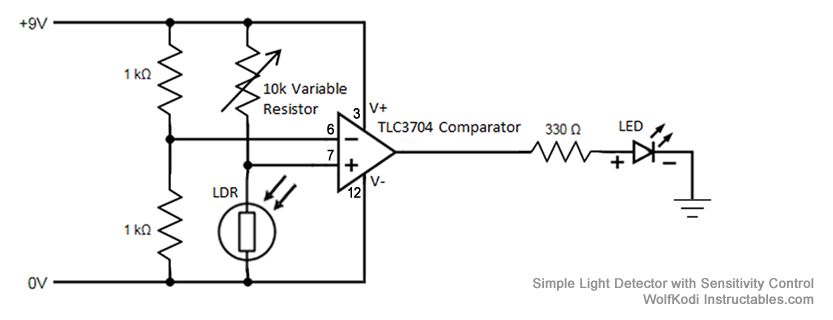
A comparator circuit typically utilizes operational amplifiers (op-amps) configured to compare two input voltage levels. The output of the comparator indicates which of the two input voltages is higher. The circuit consists of two main inputs, referred to as the inverting (-) and non-inverting (+) inputs. The non-inverting input receives one voltage signal, while the inverting input receives the other.
In this specific schematic, the 1K resistors likely serve as part of a voltage divider or feedback network, which can help set reference levels or control the gain of the comparator. The output of the comparator is usually a digital signal that swings between the supply voltage levels, indicating the comparison result. If the voltage at the non-inverting input exceeds that of the inverting input, the output will transition to a high state, typically close to the positive supply voltage. Conversely, if the voltage at the inverting input is higher, the output will drop to a low state, usually near ground.
Additional components may include power supply connections, decoupling capacitors for stability, and possibly indicators such as LEDs to visually represent the output state. The schematic may also specify additional operational parameters such as input voltage ranges, output load capabilities, and response times, which are crucial for ensuring the comparator functions correctly within its intended application.The schematic diagram for the circuit is given in the picture above. Like its name suggests, a comparator compares two given voltages. The pair of 1K.. 🔗 External reference
Related Circuits
The lamps are usually used as ballast or electronic ballast inverter. Here it is used to reduce voltage capacitor reactance. Interesting is also the method of ignition of the auxiliary electrodes involved over 150 Ohm resistors. To start simply...
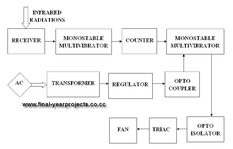
This report presents a comprehensive overview of a mini project titled "Remote Controlled Fan Regulator," developed in accordance with the curriculum requirements for the sixth semester of the Bachelor of Technology degree in Electrical and Electronics Engineering. The report...
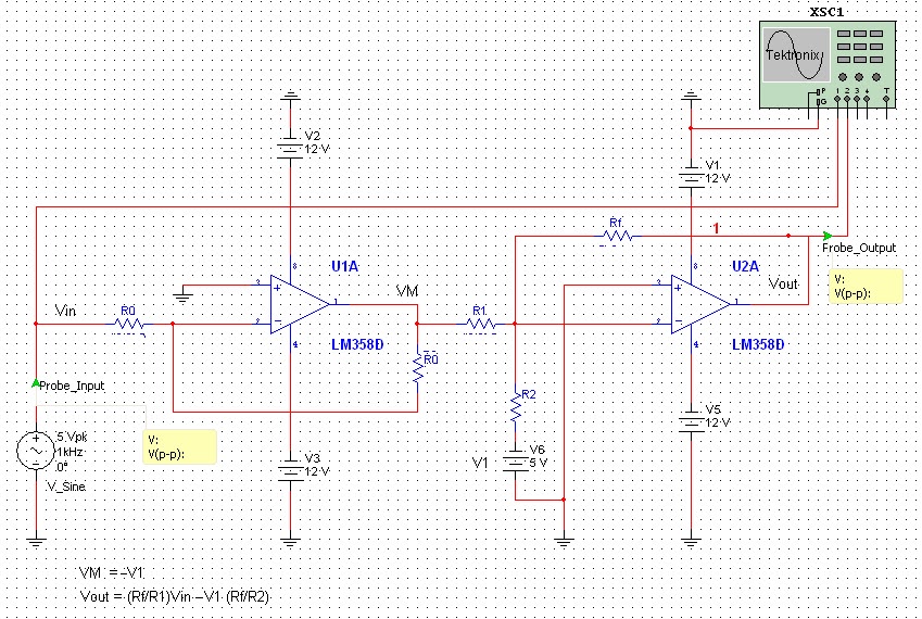
All naturally occurring phenomena such as sound, temperature, and pressure are analog in nature. To enable a microcontroller to read analog signals for the analog-to-digital conversion process using a built-in analog-to-digital converter (ADC), it is essential to condition the...
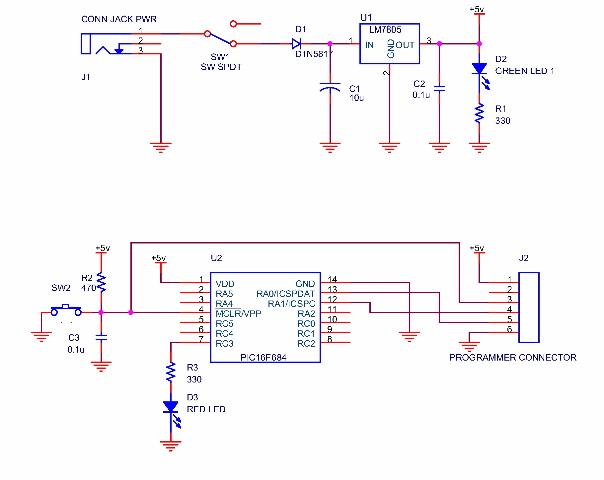
A simple program that will blink an LED. All that is required is a basic JDM programmer, and the setup is ready to go. The circuit requires a power supply, and while a good power generator is recommended, a...
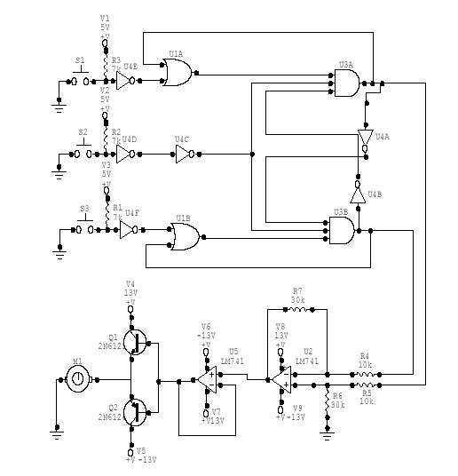
This DC Motor Controller circuit will control a 12V dc motor. The system will have three pushbuttons: a START button, a REVERSE button and a STOP button. Initially, the motor must not be running. When the START button is...
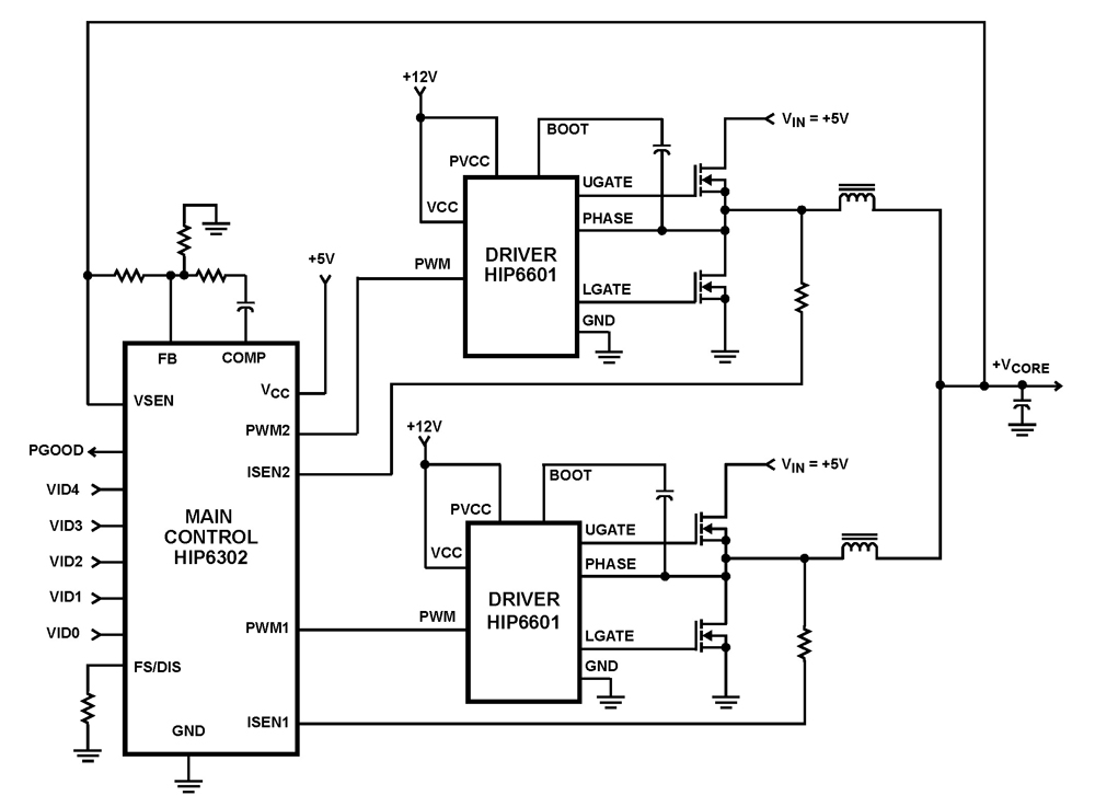
The HIP6302 Multiphase PWM control IC, along with its companion gate drivers (HIP6601, HIP6602, or HIP6603) and Intersil MOSFETs, delivers a precise voltage regulation system for advanced microprocessors. Multiphase power conversion represents a significant advancement over traditional single-phase converter...