
simple microphone preamplifier
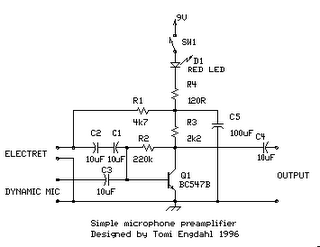
The one-transistor amplifier circuit described operates efficiently within a specified range of input signals. The transistor, typically a general-purpose NPN type, is configured in a common-emitter arrangement, which provides the desired voltage gain. The gain can be adjusted by changing the values of the resistors connected to the transistor's base and collector.
The dynamic microphone input is connected to the base of the transistor through capacitors C1, C2, and C3, which ensure that any DC bias from the microphone does not affect the transistor operation. The use of these capacitors allows only the AC audio signal to pass through, effectively blocking any unwanted DC offset.
Resistor R1 is essential for the electret microphone, as it supplies the necessary bias current for the internal amplifier of the microphone capsule. This allows the microphone to convert sound waves into electrical signals efficiently. The design considerations for the circuit also include the selection of R4 and C5, which act as a low-pass filter, effectively reducing high-frequency noise that may be present in the power supply.
The LED indicator (D1) serves a dual purpose: it not only indicates that the circuit is powered but also provides a visual cue that the amplifier is operational. The inclusion of the LED in the circuit design ensures that users can easily ascertain the status of the device.
The choice of housing the circuit in a metal box is significant, as it provides shielding from electromagnetic interference (EMI) and radio frequency interference (RFI), which can degrade the audio signal quality. Mounting the input jacks and controls on the front panel allows for easy access and usability, making the circuit suitable for various applications, including live sound reinforcement and recording.
Overall, this simple one-transistor amplifier circuit is an effective solution for amplifying audio signals from dynamic and electret microphones, making it a valuable component in audio processing systems.The circuitis a simple one transistor amplifier with amplification of about 30-40 dB (depends on transitor, temperature and voltage). The dynamic mic input is just a simple one transistor amplifier circuit with nothing special in it. LED D1 is inthe circuitto show thatthe circuitoperates. The voltage drop caused by LED (around 1. 8V for RED led) ha s been taten in account when designing theamplifier circuitbuilt around Q1. Resistor R4 and capacitor C5 make a filter to filter out possible noise from battery or other power source which is used tofeedthis circuit. Capacitors C1, C2 and C3 are used to block the DC bias on Q1 base to flow out of microphone input to microphone (the polarity of all capactors is straigh line = + and curved line = -).
Electret microphone input has a resistor R1 fo feeding current through electret microphone capsule when it is connected to the electret microphone input. Electret microphone needs some current (about 1 mA) flowing through it to operate, because there is asmall amplifier circuitinside the microphone capsule.
This circuit is suitable for all typical cheap electret capsules which available from any electronic component shop. Because electret microphones have higher signal level output, it is quite easy to overdrive the amplifier when you shout to electret microphone.
The circuitis bet to build to a small metal box like in the picture above. Put the 9V battery inside the case too. Battery power and metal box keep external noise and interference sources away. I used standard 6. 3 mm jack for dynamic microphone and 3. 5 mm mono jack for electret micrphone both installed to from, panel of the metal box. The LED and power switches are also installed tofront panel. 🔗 External reference
Related Circuits
The design of the digital logic probe centers around a pair of complementary bipolar transistors, which, in this application, are used as electronic switches. The digital logic probe is a diagnostic tool utilized for testing and analyzing digital circuits. The...
This circuit is primarily designed to provide a microphone input for standard home stereo amplifiers. Utilizing a battery supply minimizes the risk of low-frequency hum interference from mains power, simplifying the connection to the amplifier by eliminating the need...
A brief background is provided, indicating a basic understanding of electronics, including knowledge of component functions and schematic reading, but lacking further expertise. The circuit in question appears to involve fundamental electronic components, which may include resistors, capacitors, diodes, transistors,...
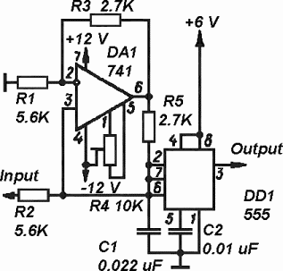
The timer is utilized in a conventional setup, with the exception that the timing resistor has been substituted with a current source derived from the operational amplifier DA1 (741). This modification enables the achievement of excellent linearity, exceeding 3%....
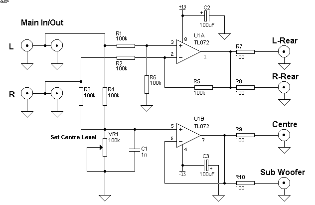
Simple Surround Sound Decoder. Introduction This surround-sound decoder is based on the Hafler principle, first discovered by David Hafler sometime in the early 1970s. The original idea. The simple surround sound decoder utilizes the Hafler principle to create an immersive...
In certain situations, it is beneficial to enhance the range of available control, and this circuit serves that purpose by receiving the infrared (IR) signal from a remote control and re-transmitting it, potentially around corners or into other rooms....