
Simple Parking Sensor Using LM324
The parking sensor circuit utilizes ultrasonic technology to detect obstacles and provide visual feedback to the driver through the LEDs. The transmitter emits ultrasonic waves, which travel until they encounter an object. The waves then reflect back to the receiver, where the time taken for the echo to return is measured. This time interval is directly proportional to the distance of the object from the sensor.
In this design, the transmitter typically consists of an ultrasonic transducer that generates sound waves at a frequency above the audible range. The receiver, which may also be an ultrasonic transducer, captures the returning sound waves. A microcontroller or a dedicated signal processing circuit interprets the received signals and determines the distance based on the speed of sound.
The LED indicators serve as a user-friendly interface, providing real-time feedback on the proximity of obstacles. For example, LED D5 could signal a safe distance, while D6 and D7 indicate progressively closer distances, alerting the driver to take caution as they approach an object. The use of multiple LEDs allows for a visual gradient of distance, enhancing situational awareness while reversing.
Power supply considerations for the circuit are also crucial, as the sensors and microcontroller require a stable voltage source. Typically, a 5V power supply is adequate for these components. Additionally, incorporating resistors in series with the LEDs ensures proper current flow, preventing damage to the LEDs and maintaining appropriate brightness levels.
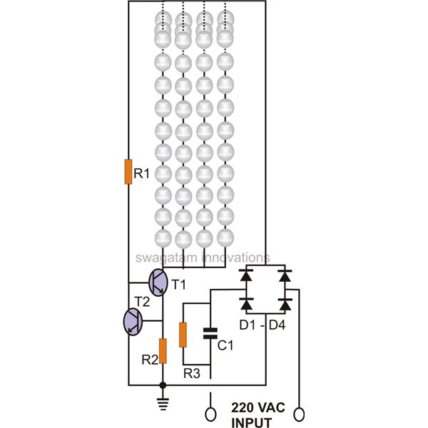
Overall, this parking sensor circuit diagram illustrates a practical and effective solution for enhancing vehicle safety during reverse maneuvers, utilizing simple electronic components to achieve reliable distance sensing.Circuit diagram is a simple parking sensors, sensing the distance between where the rear bumper of the car and obstacles behind the car. In the circuit diagram there are two parts to the scheme and the scheme for the transmitter receiver.
Distance can be understood from a combination of LEDs (D5 to D7) glowing. At 25cm D7 akan beam, 20 cm in e6 . 🔗 External reference
Related Circuits
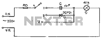
The figure illustrates a basic dimming lights circuit. The light intensity is controlled by a multi-speed control switch, designated as K. When switch K is set to position "1," the lights are turned off. In position "2," the light...
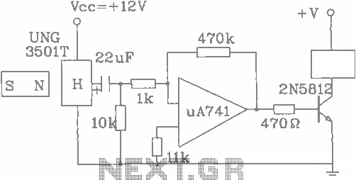
The UGN-3501T Hall sensor features a highly sensitive counter circuit diagram, allowing it to detect very small changes in magnetic fields. This capability enables the detection of ferrous metals. Utilizing this characteristic, it can be employed to count loads....
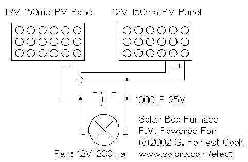
I decided to make a commercial surface mount PC board using the LED2 sensor concept. It is quite sensitive and can track to a few degrees of accuracy in bright sunlight. If a blocking shadow is used the accuracy...
This code lock circuit is an electronic combination lock designed for daily use. It only responds to the correct sequence of four digits entered remotely. If an incorrect key is pressed, the lock resets. The lock code can be...
The circuit of a current-controlled LED tube light employs high-voltage transistors to implement the necessary current control operation based on a fundamental principle. A resistor (R2) is utilized to convert the increasing current into a voltage across itself. This...
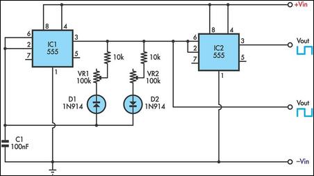
This timer utilizes two 555 integrated circuits (ICs) to adjust the desired output. The variable resistors VR1 and VR2 serve as potentiometers to modify the cycle speed. The circuit can be powered with a 9 to 12-volt power supply,...
Warning: include(partials/cookie-banner.php): Failed to open stream: Permission denied in /var/www/html/nextgr/view-circuit.php on line 713
Warning: include(): Failed opening 'partials/cookie-banner.php' for inclusion (include_path='.:/usr/share/php') in /var/www/html/nextgr/view-circuit.php on line 713