
Simple peak detector circuit using LM393. Uses minimum components and have good performance
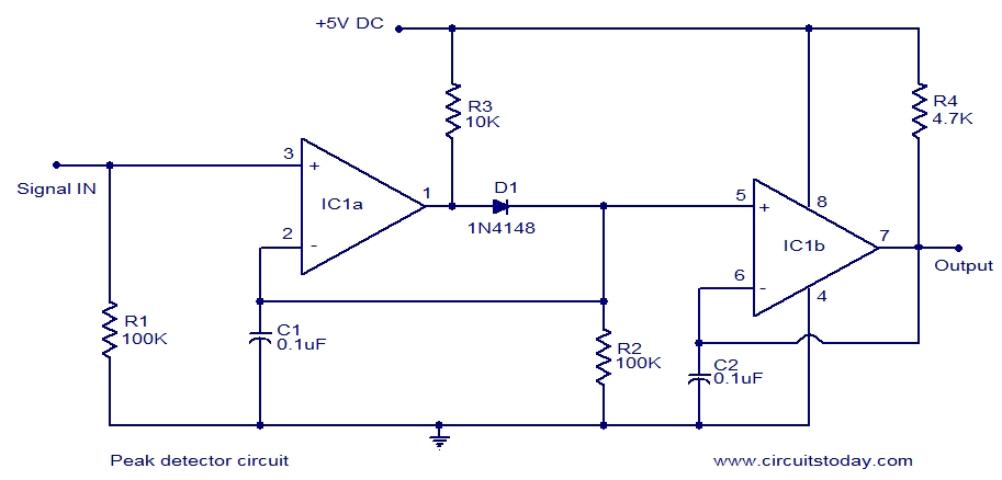
The LM339-based peak detector circuit is designed to capture and hold the peak value of an input signal. This circuit is particularly advantageous for applications where monitoring the maximum voltage level of a fluctuating signal is necessary. The LM339 integrated circuit serves as a dual comparator, allowing it to compare the input signal against a reference voltage.
The circuit typically consists of the LM339, a capacitor, and a resistor. The input signal is fed into one of the comparator inputs, while the second input is connected to a reference voltage, which can be set using a voltage divider. When the input signal exceeds the reference voltage, the output of the comparator switches states, allowing the capacitor to charge to the peak value of the input signal.
To ensure that the peak value is held, a diode is often included in the circuit. This diode prevents the capacitor from discharging back through the comparator, thus maintaining the peak voltage until it is manually reset or until the input signal drops below a certain threshold.
The circuit operates efficiently from a single 5V DC supply, making it suitable for low-power applications. The simplicity of construction, combined with the effectiveness of the LM339 as a comparator, makes this peak detector circuit a popular choice for various electronic projects and signal processing applications.LM339 based peak detector circuit.Simple and easy to construct. Operates from 5V DC single supply. LM339 is a dual comparator.. 🔗 External reference
Related Circuits

This 200-watt audio amplifier circuit diagram is based on the STK4050V high-power audio amplifier IC, designed to deliver up to 200 watts of audio power on a single channel. The STK4050V 200-watt audio amplifier circuit is pin-compatible with other...
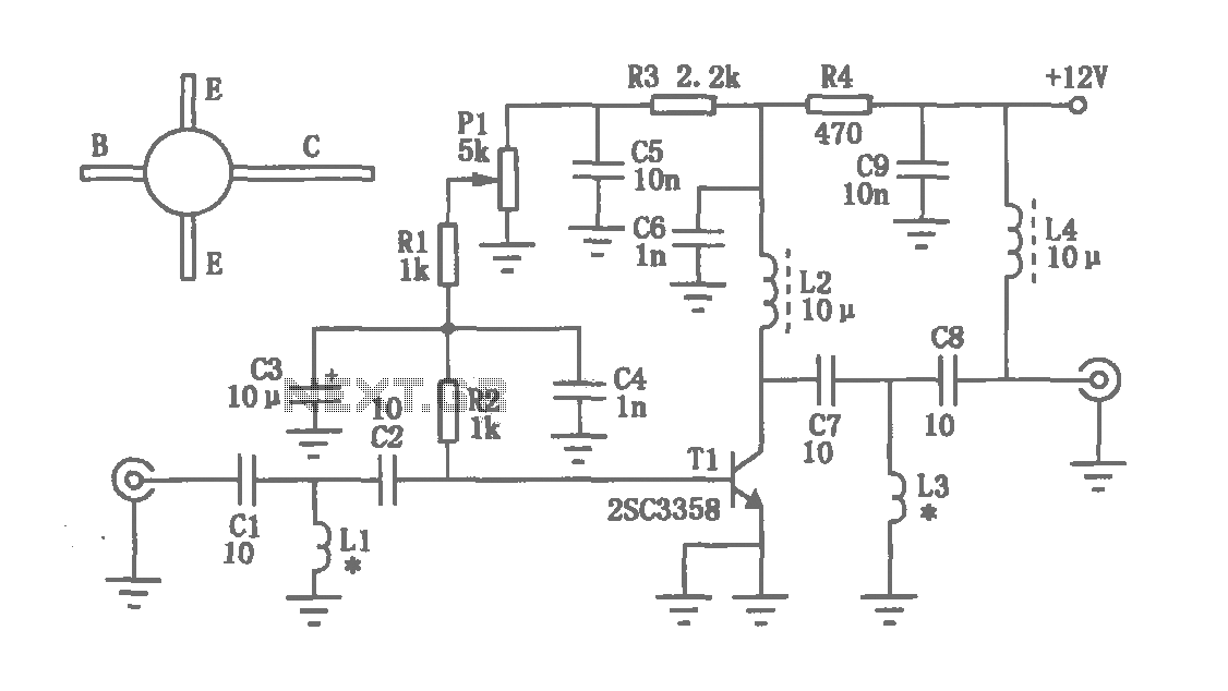
The circuit depicted in the figure operates within a frequency range of 400 to 850 MHz, designed as a UHF amplifying circuit. For optimal performance and results, it is recommended that the circuit be manufactured using silver-tin processing techniques. The...

This is a simple high-pass filter that performs filtering at high frequencies. It can only change these frequencies using the IC 741, which is an integrated circuit operational amplifier used in the circuit. The high-pass filter designed with the IC...
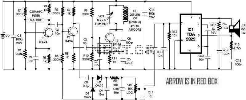
This is a simple metal detector utilizing a TDA2822 and several NPN transistors. An arrow indicates the signal flow direction from the Emitter of transistor T3 to the 10nF capacitor C4, which is opposite to the typical left-to-right flow...
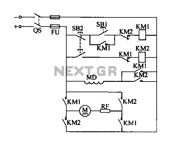
A DC motor reverse brake circuit is presented. To initiate braking, the stop button (SB2) is pressed, which disconnects the move-off contact, causing KM1 to lose power and release. Subsequently, the brake contactor (KM2) is activated. KM2 is designed...
The modem off indicator is designed specifically for avid Internet users. The circuit for this indicator is remarkably simple, and its simplicity may lead to significant cost savings by providing a clear visual indication of whether the telephone line...
Warning: include(partials/cookie-banner.php): Failed to open stream: Permission denied in /var/www/html/nextgr/view-circuit.php on line 713
Warning: include(): Failed opening 'partials/cookie-banner.php' for inclusion (include_path='.:/usr/share/php') in /var/www/html/nextgr/view-circuit.php on line 713