
Simple-power-supply
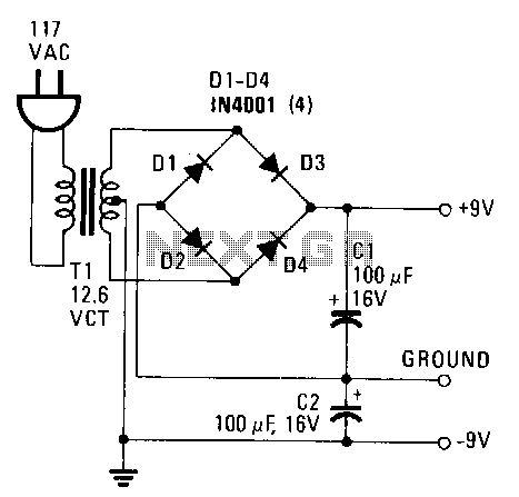
This power supply provides both +9 V and -9 V outputs to replace two 9-V batteries. The rectifier circuit consists of two separate full-wave rectifiers, each connected to the secondary winding of the transformer. The first full-wave rectifier, made up of diodes D1 and D2, produces +9 V, while the second, comprising diodes D3 and D4, generates -9 V. Each diode in the pairs rectifies 6.3 Vac, which is half the secondary voltage, and charges the corresponding filter capacitor to the peak value of the AC waveform, approximately 6.3 x 1.414, yielding around 8.9 V. Additionally, each diode must have a Peak Inverse Voltage (PIV) rating that is at least twice the peak voltage from the transformer, calculated as 2 x 8.9, resulting in a required rating of about 18 V. The 1N4001 diode has a PIV rating of 50 V.
The described power supply circuit effectively replaces two 9-V batteries by providing a stable dual output of +9 V and -9 V. The architecture relies on a transformer, which steps down the voltage from the mains supply to a lower AC voltage suitable for the application. The secondary winding of the transformer outputs 6.3 Vac, which is then processed by two full-wave rectifiers.
The first full-wave rectifier, utilizing diodes D1 and D2, converts the AC voltage into a positive DC output. The second full-wave rectifier, consisting of diodes D3 and D4, performs the same function but for the negative output. The diodes are arranged in such a way that during each half-cycle of the AC waveform, one diode conducts while the other blocks, allowing for efficient rectification.
The peak voltage across the filter capacitors is a critical factor, as it determines the maximum voltage that can be safely handled by the diodes. The calculation of approximately 8.9 V for the peak voltage indicates that the diodes must be rated for higher voltages to prevent breakdown. The selection of the 1N4001 diodes is appropriate due to their PIV rating of 50 V, which provides a substantial margin above the required 18 V, ensuring reliability and longevity in operation.
In summary, this power supply circuit design is robust and well-suited for applications requiring dual polarized voltage outputs. The careful selection of components, particularly the diodes with adequate PIV ratings, enhances the overall performance and safety of the circuit.This power supply delivers plus and minus 9 V to replace two 9-V batteries. The rectifier circuit is actually two separate full-wave rectifiers fed from the secondary of the transformer. One full-wave rectifier is composed of diodes D1 and D2, which develop +9 V, and the other is composed of D3 and D4, which develop -9 V.
Each .diode from every pair rectifies 6.3 Vac, half the secondary voltage, and charges the associated filter capacitor to the peak value of the ac waveform, 6.3 x 1.414 ~ 8.9 V. Each diode should have a PIV, Peak Inverse "Voltage, rating that is at least twice the peak voltage from the transformer, 2 x 8.9 ~ 18 V. The 1N4001 has a PIV of 50 V. 🔗 External reference