
Simple RS232 Serial Interface Circuit

The RS232 serial interface circuit is designed to facilitate communication between a microcontroller and other serial devices. The 18F4520 microcontroller, a member of the PIC family, is programmed to manage the serial data flow and control the state of connected LEDs. The microcontroller operates at a supply voltage of +5V, ensuring compatibility with the digital logic levels of the system. The circuit's power regulation is achieved using a simple voltage regulator that steps down the +9V battery supply to +5V, ensuring stable operation of the microcontroller and other components.
The MAX233A level shifter is a crucial component in this circuit, as it enables the conversion of logic levels between the microcontroller and RS232 devices. The RS232 standard specifies signal levels of +12V for a logical '1' and -12V for a logical '0', which are significantly higher than the logic levels used by the microcontroller. The MAX233A handles this conversion seamlessly, allowing for reliable communication. The device includes built-in charge pumps that generate the necessary negative voltage from the positive supply, eliminating the need for additional components.
The DB-9 connector serves as the interface point for connecting the circuit to external RS232 devices. It provides the necessary pins for transmitting and receiving data, as well as control signals. The TXout pin from the microcontroller connects to the TXin pin of the RS232 device, while the RXout pin from the RS232 device connects to the RXin pin of the microcontroller. This configuration allows for bidirectional communication.
In summary, the RS232 serial interface circuit effectively bridges the communication gap between a microcontroller and RS232-compatible devices. The combination of the 18F4520 microcontroller, MAX233A level shifter, and DB-9 connector ensures reliable data transmission and reception, while the +5V power regulation supports stable operation of the entire system. This design is suitable for various applications requiring serial communication, including data logging, remote control, and device interfacing.The circuit for the rs232 serial interface is of mild complexity. The main parts of the circuit are the 18F4520, MAX233A and DB-9 Connector and these portions of the circuit will be described briefly below. This is a basic +5v power regulator circuit for the digital signals/components. All components in this circuit use this regulated +5v for po wer. The input is simply from a +9v battery. The PIC has two man chores for this circuit. The first is receiving and sending RS232 serial communication commands and the second is turning off and on specific LEDs depending on which command is received. The MAX233A IC acts more like a translator for going from the digital +5v/+0v and into the RS232 +12v/-12v signals.
This `translation` is necessary in order to create the proper RS232 signals for the receiver to understand. Outgoing Signals are translated through the TXin/TXout and incoming signals are translated through the RXin/RXout pins.
🔗 External reference
Related Circuits

The circuit has four inputs. The voltage gain between each input and the output is maintained at unity by the relative values of the 470 kΩ input resistor and the 470 kΩ feedback resistor. The described circuit operates as a...

The output frequency of the voltage-controlled oscillator (VCO), U1, varies inversely with the input voltage. With a 1 V input, the oscillator output frequency is approximately 1500 Hz; with a 5 V input, the output frequency decreases to around...
This circuit functions as a night lamp when a wall mains socket is unavailable for plugging in a continuously operating small neon lamp device. To minimize battery consumption, it utilizes a single 1.5V cell, and a simple voltage doubler...
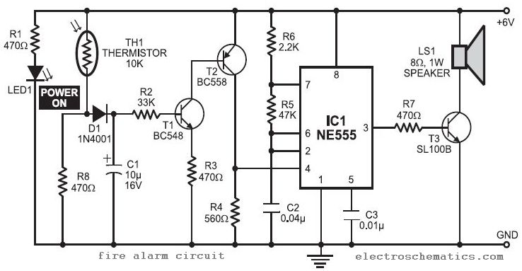
In this fire alarm circuit project, a thermistor functions as the heat sensor. When the temperature rises, its resistance decreases, and conversely, when the temperature falls, its resistance increases. Under normal conditions... In this fire alarm circuit, the thermistor is...
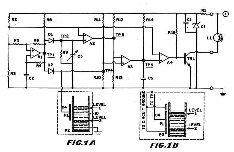
Figure 1 (A) depicts the circuit diagram of one embodiment of the fluid level detector designed. The circuit is typically powered by a 12-volt automobile battery, which is reduced to a 5-volt DC source using a voltage regulator consisting...
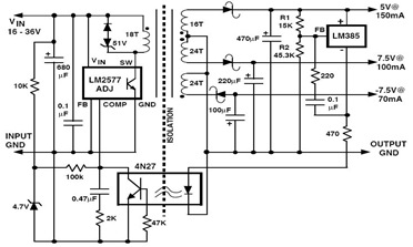
The following figure illustrates an example of a three-output flyback regulator constructed using the LM2577, which features electrical isolation between the input and output voltages. The circuit diagram specifies a voltage of 5V. Electrical isolation between the input and...