
Simple sound trigger for cameras and flashes
The sound trigger circuit is designed to activate a camera or flash unit in response to sound, making it particularly useful for capturing high-speed events such as balloon pops or other quick occurrences. The fundamental components of this circuit typically include a microphone, an amplifier, a comparator, and a relay or transistor to control the camera or flash.
The microphone serves as the initial sensor, detecting sound waves and converting them into an electrical signal. This signal is then amplified by an operational amplifier (op-amp) to ensure it is strong enough for further processing. The amplified signal is fed into a comparator, which is set to trigger when the sound level exceeds a predefined threshold. This threshold can be adjusted to suit various environments and sound levels.
Upon activation, the comparator output switches from low to high, which can be used to drive a transistor or relay. This component acts as a switch that closes the circuit to the camera or flash, initiating the capture of an image. The relay is particularly useful for isolating the camera's circuitry from the sound trigger circuit, protecting sensitive components from potential damage.
Additional features may include adjustable sensitivity controls, delay timers, or LED indicators to provide visual feedback when the trigger is activated. Power supply options for the circuit can vary, with battery-operated designs being common for portability, while wall adapters may be used for stationary setups.
This sound trigger circuit not only enhances the photography experience but also opens up opportunities for creative experimentation in capturing fleeting moments that would otherwise be difficult to document.This acticle describes how to build a simple yet effective sound trigger for cameras or flashes. The circuit allows to experiment with high-speed photography.. 🔗 External reference
Related Circuits
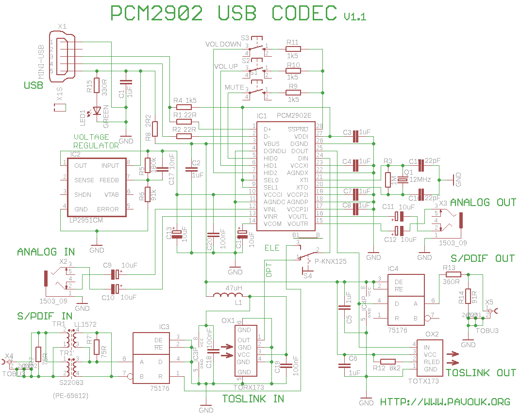
This is a USB sound card featuring the PCM2902 chip. It was designed to test the D/A converters and includes a simple circuit based on the PCM2902. The sound card is equipped with analog input and output, an electrical...
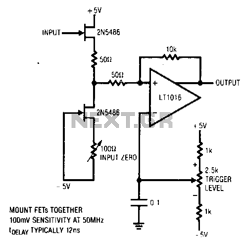
This circuit features a stable trigger with a sensitivity of 100 mV at 50 MHz. It utilizes FETs to create a high-speed buffer, while the LT1016 compares the output of this buffer to the voltage at the trigger level...
The basic circuit using the L293 forms an H-Bridge driver, as shown in Figure 1, is designed for controlling inductive loads like DC motors. External diodes are necessary for suppressing back EMF. The MiniBoard utilizes the L293D, which features...
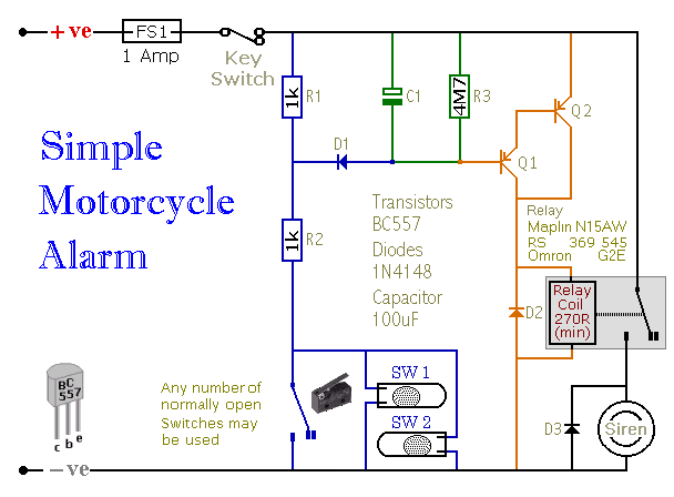
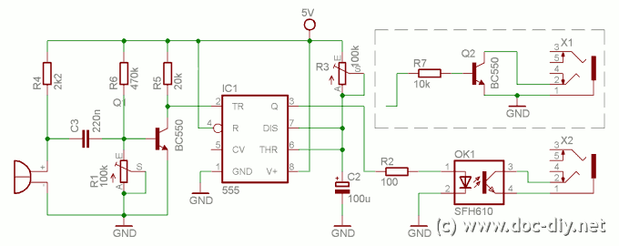
When one of the switches is closed, the base of Q1 is connected to ground through D1 and R2. This activates Q1, which in turn activates Q2. Q2 connects the positive side of the relay coil to the supply...
In appliances that require alternating current, NiCad (NiCd) rechargeable batteries still demonstrate significant performance advantages compared to NiMH and lithium batteries. The charger circuit is critical in handling incorrect polarity of the battery placement. The core of this battery...
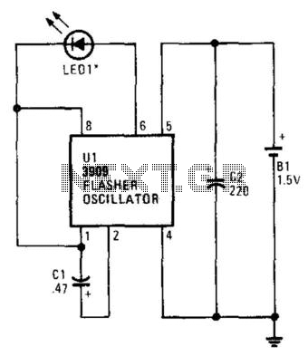
The flash rate of the IR diode is determined by the value of CI, a 220-µF capacitor that sets the oscillation rate at 1 Hz per second. Reducing CI will increase the frequency of the circuit, while larger values...
Warning: include(partials/cookie-banner.php): Failed to open stream: Permission denied in /var/www/html/nextgr/view-circuit.php on line 713
Warning: include(): Failed opening 'partials/cookie-banner.php' for inclusion (include_path='.:/usr/share/php') in /var/www/html/nextgr/view-circuit.php on line 713