
Simple Transistor Tester
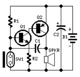
The circuit described is a high-gain amplifier configured to produce a flashing LED output based on the feedback loop established by the components involved. The key components include a high-gain amplifier, an LED, a capacitor (10 µF), and a resistor (330 kΩ). The flashing rate of the LED is influenced by the time constant created by the capacitor and resistor, which determines the charge and discharge cycles of the capacitor.
In this circuit, the high-gain amplifier is typically implemented using a transistor or an operational amplifier. The feedback mechanism allows for oscillation, which results in the LED flashing. The specific choice of the capacitor (10 µF) and the resistor (330 kΩ) will dictate the frequency of the oscillation, with the formula for the time period (T) being approximately T = R × C, where R is the resistance in ohms and C is the capacitance in farads.
The operation of the circuit can be altered by removing one of the transistors and replacing it with an unknown NPN transistor. The orientation of the transistor pins must match the configuration shown in the reference photo to ensure proper functionality. When correctly installed, the NPN transistor will allow the circuit to operate, causing the LED to flash as intended.
To deactivate the circuit, one of the transistors can be removed, which interrupts the feedback loop and stops the oscillation, effectively turning off the LED. This circuit can be used in various applications where a visual indicator is needed, such as in timers, alarms, or decorative lighting systems. Proper consideration should be given to the power supply voltage and current ratings to prevent damage to components.This is basically a high gain amplifier with feedback that causes the LED to flash at a rate determined by the 10u and 330k resistor. Remove one of the transistors and insert the unknown transistor. When it is NPN with the pins as shown in the photo, the LED will flash. To turn the unit off, remove one of the transistors. 🔗 External reference
Related Circuits
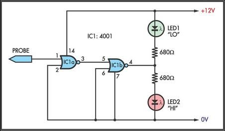
This simple logic probe has both LEDs illuminated with no signal at the input. However, due to the NOR gates connected to the probe, it indicates correctly when a high or low signal is present. It also functions correctly...
The system involves positioning a small magnet near the stalk switch SW1, which is connected to the hand or garments of the individual carrying the bag via a tiny cable. Due to the compact nature of the circuit, it...
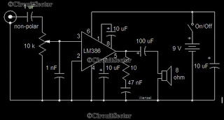
This is a simple low-power audio amplifier circuit capable of producing a power output of 1W. The mono amplifier circuit is built around the LM386 integrated circuit, which operates effectively at low voltages, even below 9V. This low-voltage amplifier...
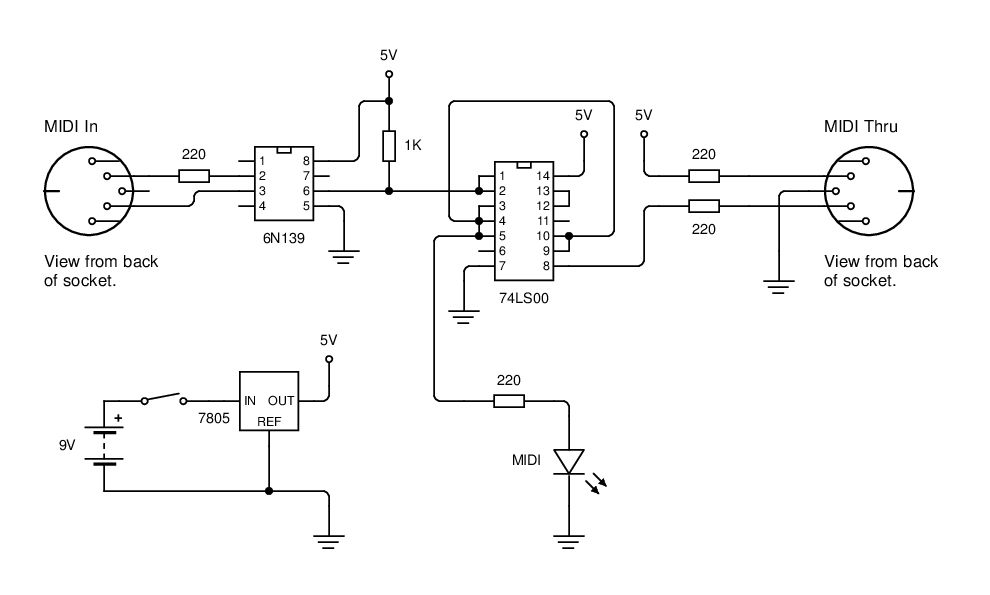
MIDI data is transmitted between instruments using a current loop, and an opto-isolator (6N139) is employed to convert this current loop into TTL pulses. The circuit utilizes the 6N139 opto-isolator to separate the MIDI signal from the receiving device, ensuring...
The first two components are passive elements, while the operational amplifier (op-amp) is an active element. The passive elements are two-terminal components, whereas the op-amp is a three-terminal component. A resistor controls the current flowing through it when a...
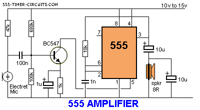
The 555 timer can function as an amplifier, operating similarly to pulse-width modulation. The component values lead the 555 to oscillate at approximately 66 kHz, a frequency to which the speaker does not respond. Instead, the speaker reacts to...