
Simple Twi-light using white LEDs
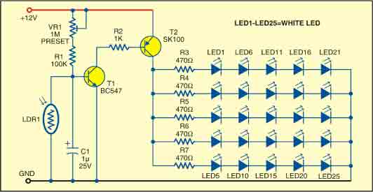
This sunlight-controlled lamp circuit is designed to automatically illuminate LEDs based on ambient light conditions. The core component, the light-dependent resistor (LDR), serves as a sensor that detects the intensity of sunlight. When exposed to light, the LDR's resistance decreases, preventing the transistors T1 and T2 from conducting. This effectively keeps the LEDs off during the day, conserving energy and extending the lifespan of the components.
In contrast, during nighttime or in low-light conditions, the LDR's resistance increases significantly. This change allows the transistors T1 and T2 to enter the conductive state, completing the circuit and enabling the 25 high-brightness white LEDs to illuminate. The use of high-brightness LEDs ensures that the lamp provides adequate light output for various applications, such as garden lighting or decorative illumination.
The circuit design incorporates resistors in series with each row of LEDs to limit the current, thus protecting the LEDs from potential damage due to excessive current flow. Proper selection of resistor values is crucial to maintain the desired brightness while ensuring the longevity of the LEDs.
Assembly of the circuit on a general-purpose PCB facilitates easy integration of components and provides a stable platform for operation. The enclosure should be designed to shield the internal components from environmental factors while allowing sufficient exposure of the LDR to sunlight. The placement of the LDR on the top of the enclosure is critical for optimal performance, ensuring it receives direct sunlight during daytime hours.
Powering the circuit with a 12V battery or adapter provides flexibility in deployment, allowing for both portable and stationary applications. The circuit can be utilized in various settings, including outdoor lighting solutions, where automatic operation based on sunlight is advantageous. Overall, this circuit exemplifies a practical application of basic electronic components to achieve an energy-efficient lighting solution.This sunlight-controlled lamp uses a light-dependent resistor (LDR) as the sunlight sensor and a total of 25 high-brightness white LEDs. Separate resistors are connected in series with each row of the LEDs. The working of the circuit is very simple. During daytime, light falls on the LDR1 and it offers a low resistance. As a result, both the trans istors (T1 and T2) do not conduct and the LEDs (LED1 through LED25) do not glow. On the other hand, during nighttime, the light does not fall on LDR1 and it offers a high resistance. As a result, transistors T1 and T2 conduct and the LEDs (LED1 through LED25) glow. Assemble the circuit on a general-purpose PCB and enclose in a cabinet. Connect the LEDs (LED1 through LED25) and LDR1 on top of the box. Place the unit such that during daytime the sunlight falls directly on LDR1. For powering the circuit, use a 12V battery or any 12V adaptor. 🔗 External reference
Related Circuits
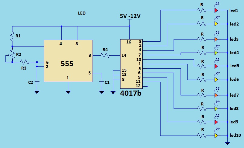
This is a LED sequencer circuit where 10 LEDs light up and turn off sequentially, creating a chasing effect. This simple circuit is suitable for designing lighting decorations on Christmas trees. It can also be used for lighting animations...

This is a simple high-frequency signal generator. By changing the inductance of the LC resonant circuit using the band switch S1, the high-frequency oscillation frequency range can be altered. The generator is divided into four frequency stages: the first...

This circuit is an infrared transmitter that operates on a low power supply of 1.5 V. The main components include two LM3909 integrated circuits, which function as an oscillator and LED flasher. Typically, this circuit is utilized as a...

The intention is to utilize this code in future projects involving 7-segment displays. For those interested in learning more about 7-segment displays, additional information can be found in a related post. 7-segment displays are widely used in electronic devices for...

The circuit utilizes the BA1404 integrated circuit from ROHM Semiconductors. The BA1404 is a monolithic FM stereo modulator that incorporates a stereo modulator, FM modulator, and RF amplifier circuitry. This FM transmitter operates within the frequency range of 76...
The LED circuit illustrated below features 25 white LEDs connected in series to a 120VAC power supply. This configuration can be adjusted to accommodate a different number of LEDs by modifying the resistor value. The specific resistance required will...
Warning: include(partials/cookie-banner.php): Failed to open stream: Permission denied in /var/www/html/nextgr/view-circuit.php on line 713
Warning: include(): Failed opening 'partials/cookie-banner.php' for inclusion (include_path='.:/usr/share/php') in /var/www/html/nextgr/view-circuit.php on line 713